Modelica. A Unified Object-Oriented Language for Physical Systems Modeling. Language Specification
Подождите немного. Документ загружается.


181
Modelica.Mechanics.MultiBody.Frames and in functions of
Modelica.Media to have no overhead for function calls such as resolving a vector
in a different coordinate system and at the same time the function can be analytically
differentiated, e.g., for index reduction needed for mechanical systems.]
LateInline Has only an effect within a function declaration
If “LateInline = true”, the model developer proposes to inline the function after
all symbolic transformations have been performed, but before common
subexpression elimination takes place.
If “
LateInline = false”, the model developer proposes to not inline the function
after symbolic transformations have been performed.
[This annotation is for example used in
Modelica.Media.Water.IF97_Utilities.T_props_ph to provide in combination with
common subexpression elimination the automatic caching of function calls.
Furthermore, it is used in order that a tool is able to propagate specific enthalpy
over connectors in the Modelica_Fluid library.]
smoothOrder_annotation:
annotation"(" smoothOrder "=" UNSIGNED_INTEGER ")"
This annotation has only an effect within a function declaration. smoothOrder defines the minimum number of
differentations of the function, in order that all of the differentiated outputs are continuous provided all input
arguments and their derivatives up to order smoothOrder are continuous [This means that the function is at least
C
smoothOrder
. smoothOrder = 1 means that the function can be differentiated at least once in order that all output
arguments are still continuous, provided the input arguments are continuous. If a tool needs the derivative of a
function, e.g. for index reduction or to compute an analytic Jacobian, the function can be differentiated
analytically at least smoothOrder times]
17.4 Annotations for Simulation Experiments
experiment_annotation:
annotation"(" "experiment" "(" [experimentOption] {, experimentOption}] ")"
experimentOption:
StartTime "=" ["+" | "-"] UNSIGNED_NUMBER |
StopTime "=" ["+" | "-"] UNSIGNED_NUMBER |
Tolerance "=" UNSIGNED_NUMBER
The experiment annotation defines the default start time (StartTime) in [s], the default stop time (StopTime) in
[s], and the default relative integration tolerance (
Tolerance) for simulation experiments to be carried out with
the model or block at hand.
17.5 Annotations for Graphical Objects
A graphical representation of a class consists of two abstraction layers, icon layer and diagram layer showing
graphical objects, component icons, connectors and connection lines. The icon representation typically visualizes
the component by hiding hierarchical details. The hierarchical decomposition is described in the diagram layer
showing icons of subcomponents and connections between these.
Graphical annotations described in this chapter ties into the Modelica grammar as follows.
graphical_annotations :
annotation "(" [ layer_annotations ] ")"
layer_annotations :
( icon_layer | diagram_layer ) ["," layer_annotations ]

182 Modelica Language Specification 3.1
Layer descriptions (start of syntactic description):
icon_layer :
"Icon" "(" [ coordsys_specification "," ] graphics ")"
diagram_layer :
"Diagram" "(" [ coordsys_specification "," ] graphics ")"
[Example:
annotation (
Icon(coordinateSystem(extent={{-100,-100}, {100,100}}),
graphics={Rectangle(extent={{-100,-100}, {100,100}}),
Text({{-100,-100}, {100,100}}, textString="Icon")}));
]
The graphics is specified as an ordered sequence of graphical primitives, which are described below. [Note that
the ordered sequence is syntactically a valid Modelica annotation, although there is no mechanism for defining an
array of heterogeneous objects in Modelica.]
17.5.1 Common Definitions
The following common definitions are used to define graphical annotations in the later sections.
type DrawingUnit = Real(final unit="mm");
type Point = DrawingUnit[2] "{x, y}";
type Extent = Point[2]
"Defines a rectangular area {{x1, y1}, {x2, y2}}";
The interpretation of "unit" is with respect to printer output in natural size (not zoomed).
All graphical entities have a visible attribute which indicates if the entity should be shown.
partial record GraphicItem
Boolean visible = true;
Point origin = {0, 0};
Real rotation(quantity="angle", unit="deg")=0;
end GraphicItem;
The origin attribute specifies the origin of the graphical item in the coordinate system of the layer in which it is
defined. The origin is used to define the geometric information of the item and for all transformations applied to
the item. All geometric information is given relative the
origin attribute, which by default is {0, 0}.
The
rotation attribute specifies the rotation of the graphical item around the point defined by the origin
attribute.
17.5.1.1 Coordinate Systems
Each of the layers has its own coordinate system. A coordinate system is defined by the coordinates of two points,
the lower left corner and the upper right corner, where the coordinates of the first point shall be less than the
coordinates of the second point [a first quadrant coordinate system].
The attribute
preserveAspectRatio specifies a constraint on the shape of components of the class. If
preserveAspectRatio is true, changing the extent of components shall preserve the aspect ratio of the
coordinate system of the class.
The attribute
initialScale specifies the default component size as initialScale times the size of the
coordinate system of the class. An application may use a different default value of
initialScale.
The attribute grid specifies the spacing between grid points which can be used by tools for alignment of points in
the coordinate system [e.g. “snap-to-grid”]. Its use and default value is tool-dependent.
183
record CoordinateSystem
Extent extent;
Boolean preserveAspectRatio=true;
Real initialScale = 0.1;
DrawingUnit grid[2];
end CoordinateSystem;
[Example: A coordinate system for an icon could for example be defined as:
CoordinateSystem(extent = {{-10, -10}, {10, 10}});
i.e. a coordinate system with width 20 units and height 20 units.]
The coordinate systems for the icon and diagram layers are by default defined as follows; where the array of
GraphicsItem represents an ordered list of graphical primitives.
record Icon "Representation of the icon layer"
CoordinateSystem coordinateSystem(extent = {{-100, -100}, {100, 100}});
GraphicItem[:] graphics;
end Icon;
record Diagram "Representation of the diagram layer"
CoordinateSystem coordinateSystem(extent = {{-100, -100}, {100, 100}});
GraphicItem[:] graphics;
end Diagram;
17.5.1.2 Graphical Properties
Properties of graphical objects and connection lines are described using the following attribute types.
type Color = Integer[3](min=0, max=255) "RGB representation";
constant Color Black = zeros(3);
type LinePattern = enumeration(None, Solid, Dash, Dot, DashDot, DashDotDot);
type FillPattern = enumeration(None, Solid, Horizontal, Vertical,
Cross, Forward, Backward, CrossDiag, HorizontalCylinder,
VerticalCylinder, Sphere);
type BorderPattern = enumeration(None, Raised, Sunken, Engraved);
type Smooth = enumeration(None, Bezier);
The FillPattern attributes Horizontal, Vertical, Cross, Forward, Backward and CrossDiag specify
fill patterns drawn with the line color over the fill color.
The attributes
HorizontalCylinder, VerticalCylinder and Sphere specify gradients that represent a
horizontal cylinder, a vertical cylinder and a sphere, respectively. The gradient goes from line color to fill color.
The border pattern attributes
Raised, Sunken and Engraved represent
frames which are rendered in a tool-dependent way.
The
smooth attribute specifies that a line can be drawn as straight line
segments (None) or using a spline (Bezier), where the line’s points specify
control points of a quadratic Bezier curve.
For lines with only two points, the
smooth attribute has no effect.
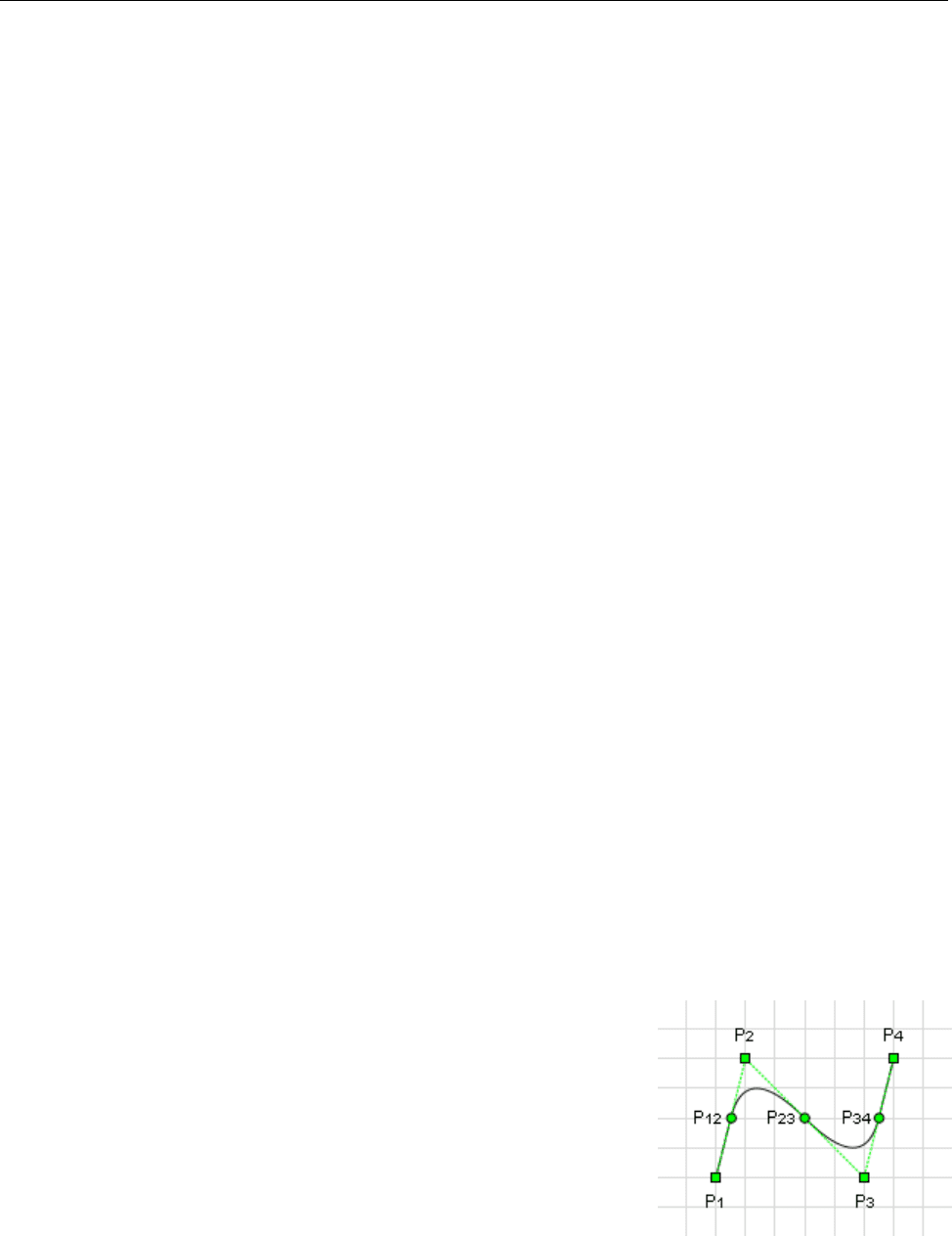
For lines with three or more points (P
1
, P
2
, …, P
n
), the middle point of each
line segment (P
12
, P
23
, …, P
(n-1)n
) becomes the starting point and ending
points of each quadratic Bezier curve. For each quadratic Bezier curve, the common point of the two line segment
becomes the control point. For instance, point P
2
becomes the control point for the Bezier curve starting at P
12
and
ending at P
23
. A straight line is drawn between the starting point of the line and the starting point of the first
quadratic Bezier curve, as well as between the ending point of the line and the ending point of the last quadratic
Bezier curve.

184 Modelica Language Specification 3.1
In the illustration above, the square points (P
1
, P
2
, P
3,
and P
4
) represent the points that define the line, and the
circle points (P
12
, P
23
, and P
34
) are the calculated middle points of each line segment. Points P
12
, P
2
, and P
23
define
the first quadratic Bezier curve, and the points P
23
, P
3
, and P
34
define the second quadratic Bezier curve. Finally a
straight line is drawn between points P
1
and P
12
as well as between P
34
and P
4
.
type Arrow = enumeration(None, Open, Filled, Half);
type TextStyle = enumeration(Bold, Italic, UnderLine);
type TextAlignment = enumeration(Left, Center, Right);
Filled shapes have the following attributes for the border and interior.
record FilledShape "Style attributes for filled shapes"
Color lineColor = Black "Color of border line";
Color fillColor = Black "Interior fill color";
LinePattern pattern = LinePattern.Solid "Border line pattern";
FillPattern fillPattern = FillPattern.None "Interior fill pattern";
DrawingUnit lineThickness = 0.25 "Line thickness";
end FilledShape;
17.5.2 Component Instance
A component instance can be placed within a diagram or icon layer. It has an annotation with a Placement
modifier to describe the placement. Placements are defined in term of coordinate systems transformations:
record Transformation
Point origin = {0, 0};
Extent extent;
Real rotation(quantity="angle", unit="deg")=0;
end Transformation;
The origin attribute defines the position of the component in the coordinate system of the enclosing class. The
extent defines the position, size and flipping of the component, relative to the origin attribute. The extent is
defined relative to the origin attribute of the component instance. Given an extent {{x1, y1}, {x2, y2}}, x2<x1
defines horizontal flipping and y2<y1 defines vertical flipping around the point defined by the origin attribute.
The
rotation attribute specifies rotation of the extent around the point defined by the origin attribute.
The graphical operations are applied in the order: scaling, flipping and rotation.
record Placement
Boolean visible = true;
Transformation transformation "Placement in the dagram layer";
Transformation iconTransformation "Placement in the icon layer";
end Placement;
If no iconTransformation is given the transformation is also used for placement in the icon layer.
[A connector can be shown in both an icon layer and a diagram layer of a class. Since the coordinate systems
typically are different, placement information needs to be given using two different coordinate systems. More
flexibility than just using scaling and translation is needed since the abstraction views might need different visual
placement of the connectors. The attribute
transformation gives the placement in the diagram layer and
iconTransformation gives the placement in the icon layer. When a connector is shown in a diagram layer, its
diagram layer is shown to facilitate opening up a hierarchical connector to allow connections to its internal
subconnectors.]
For connectors, the icon layer is used to represent a connector when it is shown in the icon layer of the
enclosing model. The diagram layer of the connector is used to represent it when shown in the diagram layer of
the enclosing model. Protected connectors are only shown in the diagram layer. Public connectors are shown in
both the diagram layer and the icon layer. Non-connector components are only shown in the diagram layer.

185
17.5.3 Extends clause
Each extends clause may have layer specific annotations which describe the rendering of the base class’ icon and
diagram layers in the subclass.
record IconMap
Extent extent = {{0, 0}, {0, 0}};
Boolean primitivesVisible = true;
end IconMap;
record DiagramMap
Extent extent = {{0, 0}, {0, 0}};
Boolean primitivesVisible = true;
end DiagramMap;
All graphical primitives are inherited from a base class. If the primitivesVisible attribute is false,
components and connections are by default visible but graphical primitives are not. The base class coordinate
system is mapped to the region specified by the attribute
extent. If the extent defines a null region (the
default), the base class coordinate system shall be fitted to the derived class coordinate system with center
alignment and respected
preserveAspectRatio of the base class.
[Example:
model A
extends B annotation(
IconMap(extent={{-100,-100}, {100,100}},primitivesVisible=false),
DiagramMap(extent={{-50,-50}, {0,0}},primitivesVisible=true)
);
end A;
]
17.5.4 Connections
A connection is specified with an annotation containing a Line primitive, as specified below. [Example:
connect(a.x, b.x)
annotation(Line(points={{-25,30}, {10,30}, {10, -20}, {40,-20}}));
]
17.5.5 Graphical primitives
This section describes the graphical primitives that can be used to define the graphical objects in an annotation.
17.5.5.1 Line
A line is specified as follows:
record Line
extends GraphicItem;
Point points[:];
Color color = Black;
LinePattern pattern = LinePattern.Solid;
DrawingUnit thickness = 0.25;
Arrow arrow[2] = {Arrow.None, Arrow.None}; "{start arrow, end arrow}"
DrawingUnit arrowSize=3;
Smooth smooth = Smooth.None "Spline";
end Line;
Note that the Line primitive is also used to specify the graphical representation of a connection.

186 Modelica Language Specification 3.1
17.5.5.2 Polygon
A polygon is specified as follows:
record Polygon
extends GraphicItem;
extends FilledShape;
Point points[:];
Smooth smooth = Smooth.None "Spline outline";
end Polygon;
The polygon is automatically closed, if the first and the last points are not identical.
17.5.5.3 Rectangle
A rectangle is specified as follows:
record Rectangle
extends GraphicItem;
extends FilledShape;
BorderPattern borderPattern = BorderPattern.None;
Extent extent;
DrawingUnit radius = 0 "Corner radius";
end Rectangle;
The extent attribute specifies the bounding box of the rectangle. If the radius attribute is specified, the
rectangle is drawn with rounded corners of the given radius.
17.5.5.4 Ellipse
An ellipse is specified as follows:
record Ellipse
extends GraphicItem;
extends FilledShape;
Extent extent;
Real startAngle(quantity="angle", unit="deg")=0;
Real endAngle(quantity="angle", unit="deg")=360;
end Ellipse;
The extent attribute specifies the bounding box of the ellipse.
For elliptic arcs,
startAngle and endAngle specify the arc prior to the stretch and rotate operations. The arc is
drawn counter-clockwise from
startAngle to endAngle, where startAngle and endAngle are defined
counter-clockwise from “3 o’clock”.
17.5.5.5 Text
A text string is specified as follows:
record Text
extends GraphicItem;
extends FilledShape;
Extent extent;
String textString;
Real fontSize = 0 "unit pt";
String fontName;
TextStyle textStyle[:];
TextAlignment horizontalAlignment = TextAlignment.Center;
end Text;
The style attribute fontSize specifies the font size. If the fontSize attribute is 0 the text is scaled to fit its
extent. Otherwise, the size specifies the absolute size. The text is vertically centered in the extent.
If the string
fontName is empty, the tool may choose a font.
The style attribute
textStyle specifies variations of the font.

187
17.5.5.6 Bitmap
A bitmap image is specified as follows:
record Bitmap
extends GraphicItem;
Extent extent;
String fileName "Name of bitmap file";
String imageSource "Base64 representation of bitmap";
end Bitmap;
The Bitmap primitive renders a graphical bitmap image. The data of the image can either be stored on an external
file or in the annotation itself. The image is scaled to fit the extent.
When the attribute
fileName is specified, the string refers to an external file containing image data. The mapping
from the string to the file is specified for some URIs in section 13.2.3. T
he supported file formats include PNG,
BMP and JPEG, other supported file formats are unspecified.
When the attribute
imageSource is specified, the string contains the image data. The image is represented as a
Base64 encoding of the image file format (see RFC 4648, http://tools.ietf.org/html/rfc4648
).
The image is uniformly scaled [to preserve aspect ratio] so it exactly fits within the extent [touching the extent
along one axis]. The center of the image is positioned at the center of the extent.
17.5.6 Variable Graphics and Schematic Animation
Any value (coordinates, color, text, etc) in graphical annotations can be dependent on class variables using the
DynamicSelect expression. DynamicSelect has the syntax of a function call with two arguments, where the
first argument specifies the value of the editing state and the second argument the value of the non-editing state.
The first argument must be a literal expression. The second argument may contain references to variables to
enable a dynamic behavior.
[Example: The level of a tank could be animated by a rectangle expanding in vertical direction and its color
depending on a variable overflow:
annotation (
Icon(graphics={Rectangle(
extent=DynamicSelect({{0,0},{20,20}},{{0,0},{20,level}}),
fillColor=DynamicSelect({0,0,255},
if overflow then {255,0,0} else {0,0,255}))}
);
]
17.5.7 User input
It is possible to interactively modify variables during a simulation. The variables may either be parameters,
discrete variables or states. New numeric values can be given, a mouse click can change a Boolean variable or a
mouse movement can change a Real variable. Input fields may be associated with a GraphicItem or a
component as an array named
interaction. The interaction array may occur as an attribute of a graphic
primitive, an attribute of a component annotation or as an attribute of the layer annotation of a class.
17.5.7.1 Mouse input
A Boolean variable can be changed when the cursor is held over a graphical item or component and the selection
button is pressed if the interaction annotation contains
OnMouseDownSetBoolean:
record OnMouseDownSetBoolean
Boolean variable "Name of variable to change when mouse button pressed";
Boolean value "Assigned value";
end OnMouseDown;

188 Modelica Language Specification 3.1
[Example: A button can be represented by a rectangle changing color depending on a Boolean variable on and
toggles the variable when the rectangle is clicked on:
annotation (Icon(graphics={Rectangle(extent=[0,0; 20,20]),
fillColor=if on then [255,0,0] else [0,0,255],
interaction={OnMouseDown(on, not on)})});
]
In a similar way, a variable can be changed when the mouse button is released:
record OnMouseUpSetBoolean
Boolean variable "Name of variable to change when mouse button released";
Boolean value "Assigned value";
end OnMouseClick;
Note that several interaction objects can be associated with the same graphical item or component.
[Example:
interaction={OnMouseDown(on, true), OnMouseUp(on, false)};
]
The
OnMouseMoveXSetReal interaction object sets the variable to the position of the cursor in X direction in the
local coordinate system mapped to the interval defined by the
minValue and maxValue attributes.
record OnMouseMoveXSetReal
Real xVariable "Name of variable to change when cursor moved
in x direction";
Real minValue;
Real maxValue;
end OnMouseMoveXSetReal;
The OnMouseMoveYSetReal interaction object works in a corresponding way as the OnMouseMoveXSetReal
object but in the Y direction.
record OnMouseMoveYSetReal
Real yVariable "Name of variable to change when cursor moved
in y direction";
Real minValue;
Real maxValue;
end OnMouseMoveYSetReal;
17.5.7.2 Edit input
The OnMouseDownEditInteger interaction object presents an input field when the graphical item or component
is clicked on. The field shows the actual value of the variable and allows changing the value. If a too small or too
large value according to the min and max parameter values of the variable is given, the input is rejected.
record OnMouseDownEditInteger
Integer variable "Name of variable to change";
end OnMouseDownEditInteger;
The OnMouseDownEditReal interaction object presents an input field when the graphical item or component is
clicked on. The field shows the actual value of the variable and allows changing the value. If a too small or too
large value according to the
min and max parameter values of the variable is given, the input is rejected.
record OnMouseDownEditReal
Real variable "Name of variable to change";
end OnMouseDownEditReal;
The
OnMouseDownEditString interaction object presents an input field when the graphical item or component
is clicked on. The field shows the actual value of the variable and allows changing the value.

189
record OnMouseDownEditString
String variable "Name of variable to change";
end OnMouseDownEditString;
17.6 Annotations for the Graphical User Interface
A class may have the following annotations to define properties of the graphical user interface:
annotation(defaultComponentName = "name")
When creating a component of the given class, the recommended component name is name.
annotation(defaultComponentPrefixes = "prefixes")
When creating a component, it is recommended to generate a declaration of the form
prefixes class-name component-name
The following prefixes may be included in the string prefixes: inner, outer, replaceable, constant,
parameter, discrete. [In combination with defaultComponentName it can be used to make it easy for users
to create inner components matching the outer declarations; see also example below]
annotation(missingInnerMessage = "message")
When an outer component of the class does not have a corresponding inner component, the string message
may be used as a diagnostic message, and then the tool may also temporarily automatically add the corresponding
inner component during translation.
[Example:
model World
annotation(defaultComponentName = "world",
defaultComponentPrefixes = "inner replaceable",
missingInnerMessage = "The World object is missing");
...
end World;
When an instance of model World is dragged in to the diagram layer, the following declaration is generated:
inner replaceable World world;
]
A declaration may have the following annotations:
annotation(unassignedMessage = "message");
When the variable to which this annotation is attached in the declaration cannot be computed due to the structure
of the equations, the string message can be used as a diagnostic message. [When using BLT partitioning, this
means if a variable “a” or one of its aliases “b = a”, “b = -a”, cannot be assigned, the message is displayed.
This annotation is used to provide library specific error messages.]
[Example:
connector Frame "Frame of a mechanical system"
...
flow Modelica.SIunits.Force f[3] annotation(unassignedMessage =
"All
Forces cannot be uniquely calculated. The reason could be that the
mechanism contains a planar loop or that joints constrain the same motion.
For planar loops, use in one revolute joint per loop the option
PlanarCutJoint=true in the Advanced menu.
");
end Frame;
]
annotation(Dialog(enable = true, tab = "General",
group = "Parameters", connectorSizing = false));
190 Modelica Language Specification 3.1
The annotations tab and group define the placement of the component or of variables in a dialog with optional
tab and group specification. If enable = false, the input field may be disabled [and no input can be given].
The value of the connectorSizing annotation must be a literal
false or true value [since if the value is an
expression, the connectorSizing functionality is conditional and this will then lead easily to wrong models]. If
connectorSizing = false, this annotation has no effect. If connectorSizing = true, the corresponding
variable must be declared with the
parameter prefix, must be a subtype of a scalar Integer and must have a
literal default value of zero [since this annotation is designed for a parameter that is used as vector dimension and
the dimension of the vector should be zero when the component is dragged or redeclared; furthermore, when a
tool does not support the connectorSizing annotation, dragging will still result in a correct model].
If
connectorSizing = true, a tool may set the parameter value in a modifier automatically, if used as
dimension size of a vector of connectors. [The connectorSizing annotation is used in cases where connections to a
vector of connectors shall be made and a new connection requires to resize the vector and to connect to the new
index (unary connections). The annotation allows a tool to perform these two actions in many cases
automatically. This is, e.g., very useful for state machines and for certain components of fluid libraries.]
Annotation “Dialog” is defined as:
record Dialog
parameter String tab = "General";
parameter String group = "Parameters";
parameter Boolean enable = true;
parameter Boolean connectorSizing = false
end Dialog;
A parameter dialog is a sequence of tabs with a sequence of groups inside them.
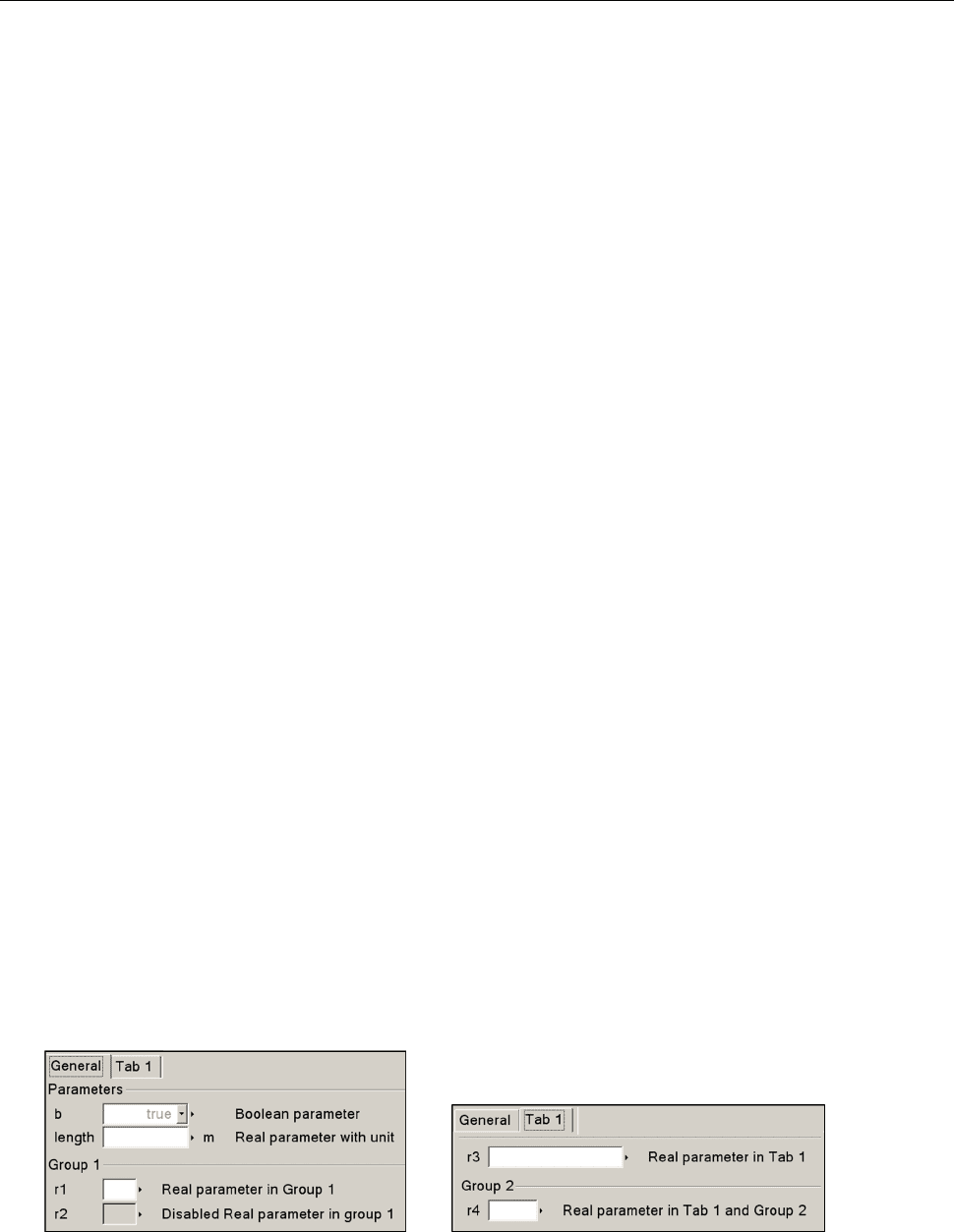
[Example:
model DialogDemo
parameter Boolean b = true "Boolean parameter";
parameter Modelica.SIunits.Length length "Real parameter with unit";
parameter Integer nInports=0 annotation(Dialog(connectorSizing=true));
parameter Real r1 "Real parameter in Group 1" annotation(Dialog(group="Group 1"));
parameter Real r2 "Disabled Real parameter in group 1"
annotation(Dialog(group="Group 1", enable = not b));
parameter Real r3 "Real parameter in Tab 1" annotation(Dialog(tab="Tab 1"));
parameter Real r4 "Real parameter in Tab 1 and Group 2"
annotation(Dialog(tab="Tab 1", group="Group 2"));
StepIn stepIn[nInports];
...
end DialogDemo;
When clicking on an instance of model DialogDemo, a menu pops up that may have the following layout (other
layouts are also possible, this is vendor specific). Note, parameter nInports is not present in the menu since it has
the “connectorSizing” annotation and therefore it should not be modified by the user (an alternative is to show
parameter nInports in the menu but with disabled input field):
The following part is non-normative text and describes a useful way to handle the connectorSizing annotation in a
tool (still a tool may use another strategy and/or may handle other cases than described below). The
recommended rules are clarified at hand of the following example which represents a connector and a model from
the Modelica.StateGraph library: