Lyons W.C. (ed.). Standard handbook of petroleum and natural gas engineering.2001- Volume 1
Подождите немного. Документ загружается.

Fishing Operations and Equipment
1115
corrosion in production wells have decreased the necessity for fishing opera-
tions in production wells.
Fishing
Tools
There are basically three categories of fishing tools. These are
(1)
those used
to define the geometry and orientations of the fish
or
junk in the borehole,
(2)
those used to recover tubular items (fish), and
(3)
those used to recover
miscellaneous items (junk).
Geometry and Orientation
Tools
The tools used to define the geometry and orientation of the fish or junk in
the borehole vary from sophisticated downhole televiewers to very simple
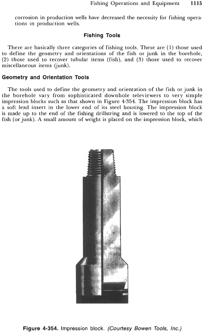
impression blocks such as that shown in Figure
4-354.
The impression block has
a soft lead insert in the lower end of its steel housing. The impression block
is made up to the end of the fishing drillstring and is lowered to the top of the
fish (or junk).
A
small amount of weight is placed on the impression block, which
Figure
4-354.
Impression block.
(Courtesy
Bowen Tools,
Inc.)
11
16
Drilling and Well Completions
places an imprint of the top of the fish on the lead insert. This imprint when
recovered enables the operator to assess the configuration of the fish and its
location in the borehole. The operator is then in a better position to select the
proper tool needed to successfully complete the fishing operation. Sophisticated
televiewers are run in the borehole much like any other logging tool. These
services are obtained from companies that specialize in such equipment.
Tubular Fishing Tools
There are two subcategories of tubular fishing tools: those that can attach to
the inside of the tubular fish and those that can attach to the outside of the
tubular fish.
Inside Fishing Tools.
Most of the fishing tools designed to catch tubular items
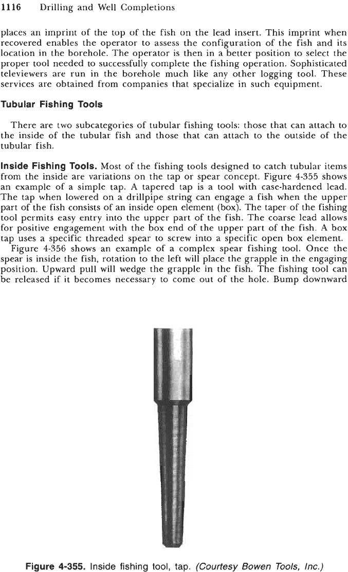
from the inside are variations on the tap or spear concept. Figure
4-355
shows
an example of a simple tap.
A
tapered tap is a tool with case-hardened lead.
The tap when lowered on a drillpipe string can engage a fish when the upper
part of the fish consists of an inside open element (box). The taper of the fishing
tool permits easy entry into the upper part
of
the fish. The coarse lead allows
for positive engagement with the box end of the upper part of the fish.
A
box
tap uses a specific threaded spear to screw into a specific open box element.
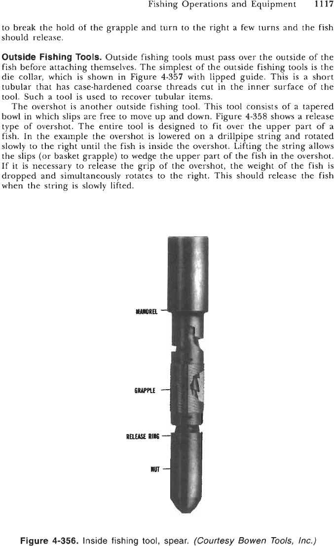
Figure
4-356
shows an example of a complex spear fishing tool. Once the
spear is inside the fish, rotation to the left will place the grapple in the engaging
position. Upward pull
will
wedge the grapple in the fish. The fishing tool can
be released
if
it
becomes necessary to come out of the hole. Bump downward
Figure
4-355.
Inside fishing
tool,
tap.
(Courtesy Bowen Tools, Inc.)
Fishing Operations and Equipment
11
17
to break the hold of the grapple and turn to the right a few turns and the fish
should release.
Outside
Fishing
TOOIS.
Outside fishing tools must pass over the outside of the
fish before attaching themselves. The simplest of the outside fishing tools is the
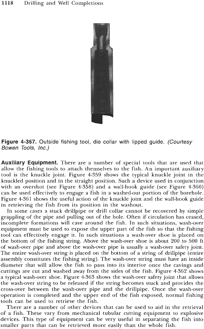
die collar, which is shown in Figure
4-357
with lipped guide. This is a short
tubular that has case-hardened coarse threads cut in the inner surface of the
tool. Such a tool is used to recover tubular items.
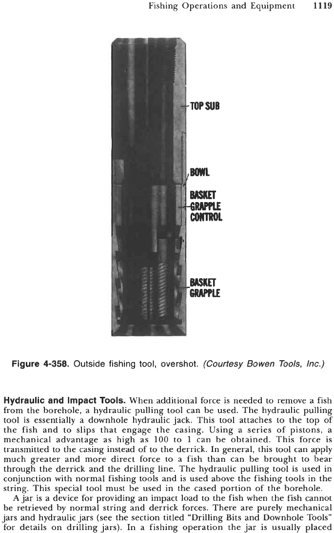
The overshot is another outside fishing tool. This tool consists of a tapered
bowl in which slips are free to move up and down. Figure
4-358
shows a release
type of overshot. The entire tool is designed to fit over the upper part of a
fish. In the example the overshot is lowered on a drillpipe string and rotated
slowly to the right until the fish is inside the overshot. Lifting the string allows
the slips (or basket grapple) to wedge the upper part of the fish in the overshot.
If it is necessary to release the grip of the overshot, the weight of the fish is
dropped and simultaneously rotates to the right. This should release the fish
when the string is slowly lifted.
Figure
4-356.
Inside fishing
tool,
spear. (Courtesy Bowen Tools, Inc.)
11
18
Drilling and Well Completions
Figure
4-357.
Outside fishing tool, die
collar
with lipped guide.
(Courtesy
Bowen
Tools,
Inc.)
Auxiliary Equipment.
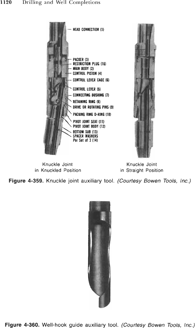
There are a number of special tools that are used that
allow the fishing tools to attach themselves to the fish. An important auxiliary
tool is the knuckle joint. Figure
4-359
shows the typical knuckle joint in the
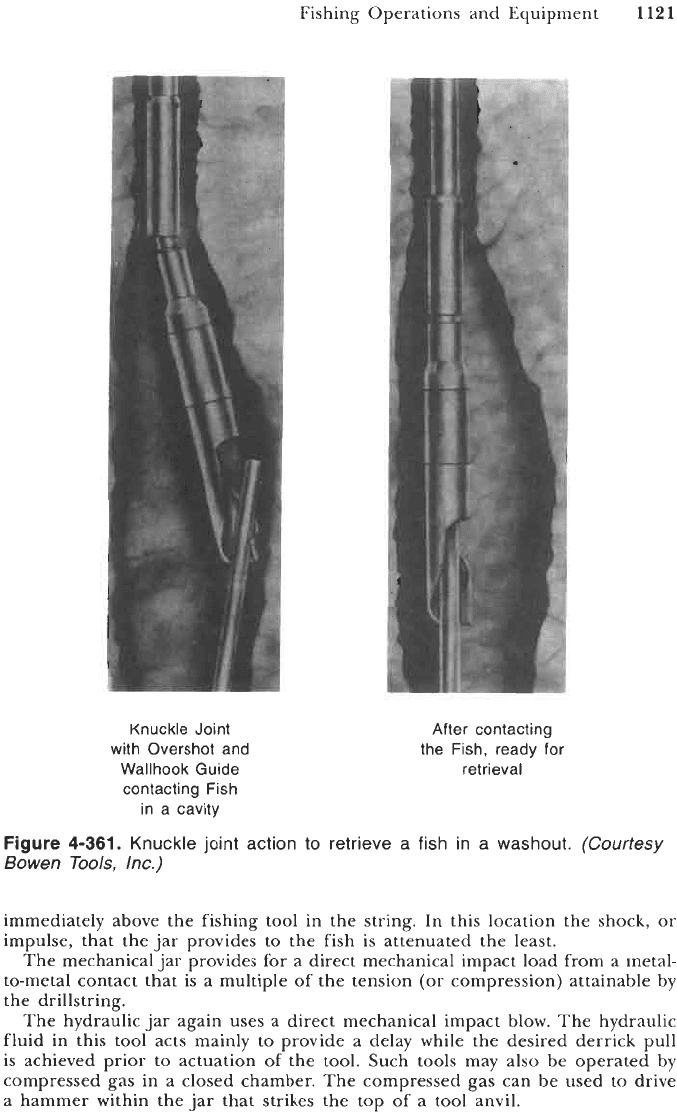
knuckled position and in the straight position. Such a device used in conjunction
with an overshot (see Figure
4-358)
and a wall-hook guide (see Figure
4-360)
can be used effectively to engage a fish in a washed-out portion of the borehole.
Figure
4-361
shows the useful action of the knuckle joint and the wall-hook guide
in retrieving the fish from its position in the washout.
In some cases a stuck drillpipe or drill collar cannot be recovered by simple
grappling of the pipe and pulling out of the hole. Often if circulation has ceased,
incomplete formations will cave around the fish. In such situations, wash-over
equipment must be used to expose the upper part of the fish
so
that the fishing
tool can effectively engage it. In such situations a wash-over shoe is placed on
the bottom of the fishing string. Above the wash-over shoe is about
200
to
500
ft
of wash-over pipe and above the wash-over pipe is usually a wash-over safety joint.
The entire wash-over string is placed on the bottom of a string of drillpipe (entire
assembly constitutes the fishing string). The wash-over string must have an inside
diameter that will allow the fish to pass into its interior once the cavings and
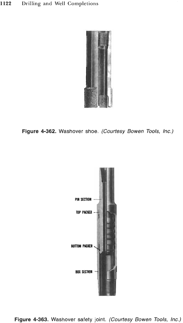
cuttings are cut and washed away from the sides of the fish. Figure
4-362
shows
a typical wash-over shoe. Figure
4-363
shows the wash-over safety joint that allows
the wash-over string to be released if the string becomes stuck and provides the
cross-over between the wash-over pipe and the drillpipe. Once the wash-over
operation is completed and the upper end of the fish exposed, normal fishing
tools can be used to retrieve the fish.
There are a number of other devices that can be used to aid in the retrieval
of a fish. These vary from mechanical tubular cutting equipment to explosive
devices. This type of equipment can be very useful in separating the fish into
smaller parts that can be retrieved more easily than the whole fish.
Fishing Operations and Equipment
11
19
Figure
4-358.
Outside
fishing
tool,
overshot.
(Courtesy Bowen Tools, lnc.)
Hydraulic and Impact
Tools.
When additional force is needed to remove a fish
from the borehole, a hydraulic pulling tool can be used. The hydraulic pulling
tool is essentially a downhole hydraulic jack. This tool attaches to the top of
the fish and to slips that engage the casing. Using a series of pistons, a
mechanical advantage as high as
100
to
1
can be obtained. This force is
transmitted to the casing instead of to the derrick. In general, this tool can apply
much greater and more direct force to a fish than can be brought to bear
through the derrick and the drilling line. The hydraulic pulling tool is used in
conjunction with normal fishing tools and is used above the fishing tools in the
string. This special tool must be used in the cased portion of the borehole.
A
jar is a device for providing an impact load to the fish when the fish cannot
be retrieved by normal string and derrick forces. There are purely mechanical
jars and hydraulic jars (see the section titled "Drilling Bits and Downhole Tools"
for details on drilling jars). In a fishing operation the jar is usually placed
1120
Drilling and Well Completions
PIGtifR
(3)
RESTRICTION
FLU6
116)
MAIM
BODY
(2)
CONTROL
PlSTOn
(4)
CONTROL
LEER
CW
(8)
coma
LMR
m
RETUNtNG
RllG
(8)
COMIEC~MG
BUSHINS
m
DRIVE
OR
ROI~~WB
p~lls
o
P~CKIMP
RING
0-RM
(im
PlVOl
1MIII
SEN
(11)
PIVOT
lOlA
BODY
(12)
BOTTOM
SUB
(13)
SPICER
WASHERS
Per
Set
01
3
(14)
Knuckle Joint
in Knuckled Position
Knuckle Joint
in Straight Position
Figure
4-359.
Knuckle joint auxiliary tool.
(Courtesy Bowen
Tools,
lnc.)
Figure
4-360.
Well-hook guide auxiliary tool.
(Courtesy Bowen
Tools,
lnc.)
Fishing Operations and Equipment
1121
Knuckle Joint
with Overshot and
Wallhook Guide
contacting Fish
in a cavity
After contacting
the Fish, ready for
retrieval
Figure
4-361.
Knuckle joint action to retrieve
a
fish in
a
washout.
(Courtesy
Bowen Tools, Inc.)
immediately above the fishing tool in the string. In this location the shock, or
impulse, that the jar provides to the fish is attenuated the least.
The mechanical jar provides for a direct mechanical impact load from a metal-
to-metal contact that is a multiple of the tension (or compression) attainable by
the drillstring.
The hydraulic jar again uses a direct mechanical impact blow. The hydraulic
fluid in this tool acts mainly to provide a delay while the desired derrick pull
is achieved prior to actuation of the tool. Such tools may also be operated by
compressed gas in
a
closed chamber. The compressed gas can be used to drive
a hammer within the jar that strikes the top
of
a tool anvil.
1122
Drilling and Well Completions
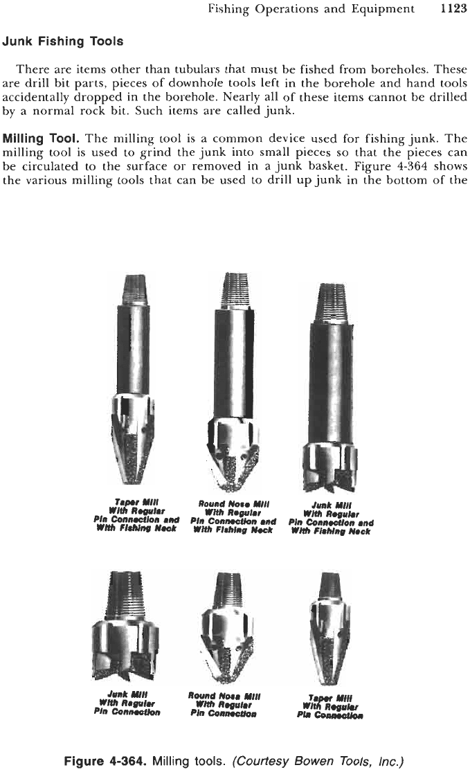
Figure
4-362.
Washover shoe.
(Courtesy Bowen Tools, Inc.)
Figure
4-363.
Washover safety joint.
(Courtesy Bowen Tools, Inc.)
Fishing Operations and Equipment
1123
Junk Fishing
Tools
There are items other than tubulars that must be fished from boreholes. These
are drill bit parts, pieces
of
downhole tools left in the borehole and hand tools
accidentally dropped in the borehole. Nearly all of these items cannot be drilled
by a normal rock bit. Such items are called junk.
Milling
Tool.
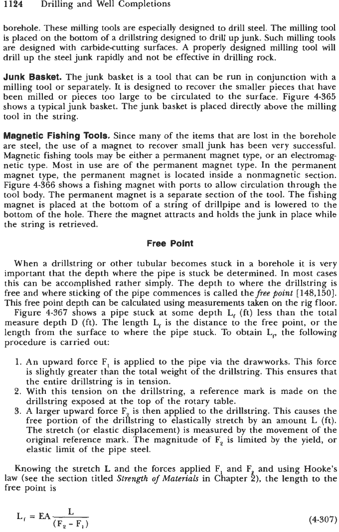
The milling tool is a common device used for fishing junk. The
milling tool is used to grind the junk into small pieces
so
that the pieces can
be circulated to the surface or removed in a junk basket. Figure
4-364
shows
the various milling tools that can be used to drill up junk in the bottom
of
the
WHI,
Rwuht
with
R.gutot
With
Re&&
Pln Connocflon
Md
Pfn Conmctlon and Pln Connwlon
ml
Wtlh
FI8hJng
Noek
WHI,
Fkhing
Nock
WMh
Fl8hing
Nock
Figure
4-364.
Milling
tools.
(Courtesy
Bowen
Tools,
lnc.)
1124
Drilling and Well Completions
borehole. These milling tools are especially designed to drill steel. The milling tool
is placed on the bottom of a drillstring designed to drill up junk. Such milling tools
are designed with carbidecutting surfaces.
A
properly designed milling tool will
drill up the steel junk rapidly and not be effective in drilling rock.
Junk Basket.
The junk basket is a tool that can be run in conjunction with a
milling tool or separately. It is designed to recover the smaller pieces that have
been milled or pieces too large to be circulated to the surface. Figure
4-365
shows a typical junk basket. The junk basket is placed directly above the milling
tool in the string.
Magnetic Fishing
Tools.
Since many of the items that are lost in the borehole
are steel, the use of a magnet to recover small junk has been very successful.
Magnetic fishing tools may be either a permanent magnet type, or an electromag-
netic type. Most in use are of the permanent magnet type. In the permanent
magnet type, the permanent magnet is located inside a nonmagnetic section.
Figure
4-366
shows a fishing magnet with ports to allow circulation through the
tool body. The permanent magnet is a separate section of the tool. The fishing
magnet is placed at the bottom of a string of drillpipe and is lowered to the
bottom of the hole. There the magnet attracts and holds the junk in place while
the string is retrieved.
Free Point
When a drillstring or other tubular becomes stuck in a borehole
it
is very
important that the depth where the pipe is stuck be determined. In most cases
this can be accomplished rather simply. The depth to where the drillstring is
free and where sticking of the pipe commences is called thefree
point
[148,150].
This free point depth can be calculated using measurements taken on the rig floor.
Figure
4-367
shows a pipe stuck at some depth
L,
(ft) less than the total
measure depth D (ft). The length
L,
is the distance to the free point, or the
length from the surface to where the pipe stuck. To obtain
L,,
the following
procedure is carried out:
1.
An upward force F, is applied to the pipe via the drawworks. This force
is slightly greater than the total weight of the drillstring. This ensures that
the entire drillstring is in tension.
2.
With this tension on the drillstring, a reference mark is made on the
drillstring exposed at the top of the rotary table.
3.
A larger upward force F, is then applied to the drillstring. This causes the
free portion of the drillstring to elastically stretch by an amount
L
(ft).
The stretch (or elastic displacement) is measured by the movement of the
original reference mark. The magnitude of F, is limited by the yield, or
elastic limit of the pipe Steel.
Knowing the stretch
L
and the forces applied F, and F, and using Hooke’s
law (see the section titled
Strength
of
Materials
in Chapter
2),
the length to the
free point is
(4-307)
