Kumar E.S. (ed.) Integrated Waste Management. V.I
Подождите немного. Документ загружается.

Hydraulic Conductivity of Steel Pipe Sheet Pile Cutoff Walls at Coastal Waste Landfill Sites
331
In this study, an evaluation method that can express the local leakage at the joint sections of
SPSP cutoff walls is discussed. The evaluation method using the equivalent hydraulic
conductivity is defined as the “UL-model”, and the evaluation method that considers the
steel pipe and joint sections, that is, the local leachate leakage, is defined as the “SP-JS-
model”. Figure 7 shows a general description of the UL-model and SP/JS-model. In the UL-
model (shown in Fig. 7(a)), equivalent hydraulic conductivities of 2.0×10
-6
, 1.0×10
-6
, 1.0×10
-7
and 1.0×10
-8
cm/s were assigned to the entire SPSP cutoff wall. In the SP/JS-model (see Fig.
7(b)), the joint sections were placed at 0.25 m intervals for steel pipes of diameter 1 m, which
represents the standard sizes of the SPSP shown in Fig. 2. Furthermore, hydraulic
conductivities were assigned to each steel pipe and joint section in the SP/JS-model such
that the entire hydraulic conductivity of the SPSP cutoff wall equals the equivalent
hydraulic conductivity assigned in the UL-model, that is, hydraulic conductivities of 2.5×10
-
6
, 1.3×10
-6
, 1.3×10
-7
and 1.3×10
-8
cm/s were assigned to the joint sections, assuming that the
hydraulic conductivity of steel pipe is infinitely small. Table 1 shows the seepage, advection
and dispersion properties assigned to each composition layer in both the models.
3. Results and discussion
3.1 Environmental feasibility of SPSP cutoff wall considering local water leakage
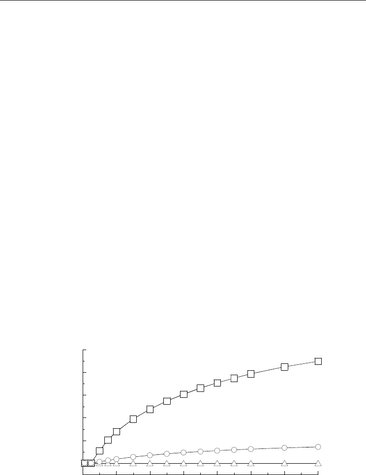
Figure 8 shows the concentration flux (the material quantity passing through a unit area in
unit time) of toxic substances leaking from the SPSP cutoff wall on the sea side. The fluxes in
the uniform layer of the UL-model and in each steel pipe and joint section of the SP/JS-
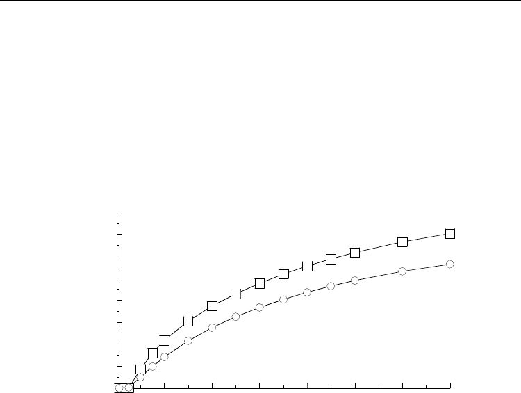
model are plotted in Fig. 8. The relationship between the elapsed time and the highest
concentration of toxic substances leaked from the SPSP cutoff wall on the sea side for both
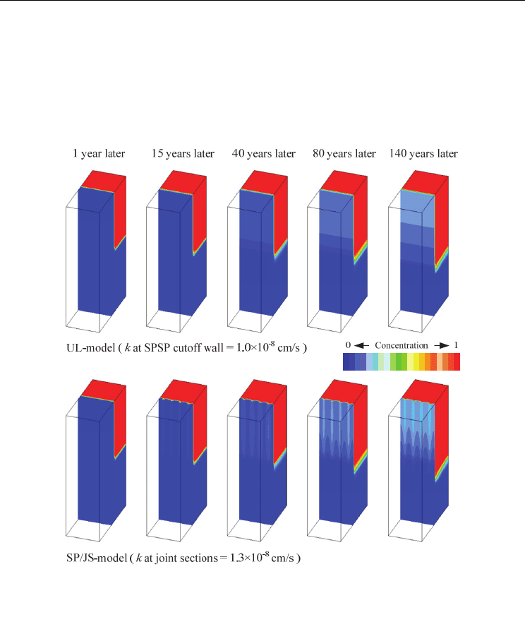
the models is shown in Fig. 9. Figure 10 illustrates the distribution of the concentration of
toxic substances leaking out from the waste layer, which is the contaminated source, for
both the models. Figure 10 expresses the distribution of the concentration on the sea side of
the SPSP cutoff wall in order to facilitate the comparison of both the models with regard to
the leakage of the toxic substance to the surroundings of the coastal landfill site.
0.000
0.001
0.002
0.003
0.004
0.005
0 20406080100120140
Concentration flux of toxic substances
leaking from SPSP cuoff wall (m/year)
Elapsed time (years)
Joint section in SP/JS-model
UL-model
Steel pipe in SP/JS-model
( k at joint section = 1.3×10
-8
cm/s )
( k at SPSP cutoff wall = 1.0×10
-8
cm/s )
Fig. 8. Concentration flux of toxic substances leaking from SPSP cutoff wall on sea side with
elapsed time for both models
Integrated Waste Management – Volume I
332
In the SP/JS-model, the concentration flux of toxic substances leaked onto the sea side of the
SPSP cutoff wall, particularly from the joint sections, is increased as compared to that of the
UL-model (see Fig. 8). The SP/JS-model can quantitatively express the concentration of toxic
substances at the joint sections of the SPSP cutoff wall, where the hydraulic conductivity is
higher than that in the steel pipe. In the UL-model, as shown in Fig. 10, the leachate leaks
uniformly from the SPSP cutoff wall onto the sea side, and this leakage tends to uniformly
increase with time. In the SP/JS-model, it being different from the UL-model, the leachate
leaks locally from the joint sections onto the sea side of the SPSP cutoff wall, and this leakage
increases locally with time at the joint sections (see Fig. 10). Consequently, the increase in the
concentration of toxic substances leaked from the SPSP cutoff wall onto the sea side is found to
occur earlier in the SP/JS-model than in the UL-model, as shown in Fig. 9.
0.00
0.02
0.04
0.06
0.08
0.10
0.12
0.14
0.16
0 20 40 60 80 100 120 140
Highest concentration of toxic substances
leaked from SPSP cutoff wall
Elapsed time (years)
Joint section in SP/JS-model
UL-model
( k at joint section = 1.3×10
-8
cm/s )
( k at SPSP cutoff wall = 1.0×10
-8
cm/s )
Fig. 9. Relationship between elapsed time and the highest concentration of toxic substances
leaked from SPSP cutoff wall on sea side for both models
For example, 70 and 110 years, respectively, are required in the SP/JS-model (the hydraulic
conductivity of the entire SPSP cutoff wall is 1.0×10
-8
cm/s) and the UL-model for the
concentration of toxic substances in the SPSP cutoff wall on the sea side to reach C=0.1,
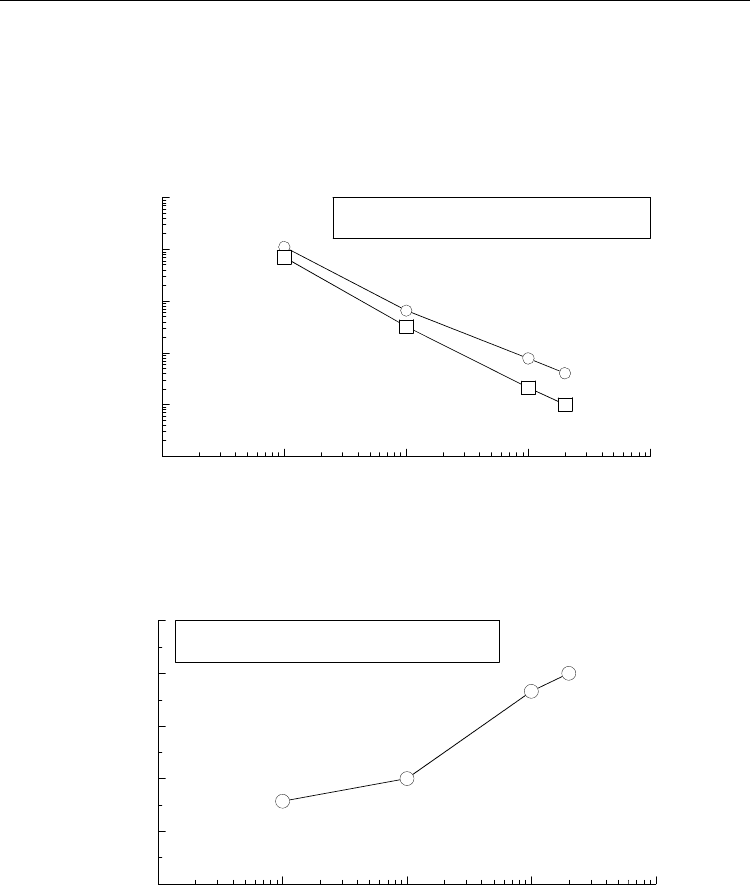
which is assumed as the assessment index. In the other analyzed conditions under which the
hydraulic conductivity of the entire SPSP cutoff wall is equivalent in both models, the
leakage of leachate is confirmed to occur earlier in the SP/JS-model than in the UL-model
due to effect of the local leakage of leachate (see Fig. 11). This tendency becomes more
remarkable with increase in the hydraulic conductivity of the entire SPSP cutoff wall (see
Fig. 12).
Thus, as mentioned above, the reproduction of the local leakage of leachate generated at the
joint sections of SPSP cutoff walls is possible by using the SP/JS-model for the evaluation of
the environmental feasibility of SPSP cutoff walls at coastal landfill sites. Furthermore, the
SP/JS-model indicates that toxic substances in concentrations exceeding the environmental
standard values are leaked out of coastal landfill sites earlier than that estimated using the
UL-model (see Fig. 9). Using the UL-model, the local leakage of leachate containing toxic
substances from the SPSP cutoff wall cannot be reproduced, although the total quantity of
the toxic substances leaked from the SPSP cutoff wall can be estimated. This provides a
safer-side estimate of the environmental feasibility from the viewpoint of the time taken for
Hydraulic Conductivity of Steel Pipe Sheet Pile Cutoff Walls at Coastal Waste Landfill Sites
333
the leakage of toxic substances. In addition, by using the UL-model, it is difficult to
quantitatively detect the generation position in the SPSP cutoff wall where the leachate
containing toxic substances are leaked. An appropriate estimation in terms of both position
and time at which the loss of environmental feasibility occurs is important in order to
control and maintain a long-term SPSP cutoff wall at coastal landfill sites. Based on the
abovementioned points, the environmental feasibility of SPSP cutoff walls must be verified
by using the SP/JS-model.
Fig. 10. Distribution of concentration of toxic substances leaking out from waste layer for
both models
3.2 Environmental feasibility of SPSP cutoff wall considering joint sections
Various types of joints are adopted for the joint sections of the SPSP cutoff walls, as shown
in Fig. 2. The types of joints for which the hydraulic performance has been reported
experimentally are the P-T joints in which the packing mortar is filled in the joint space, the
improved P-T joint in which a rubber board is installed with the mortar filling in the joint
space and the H-H joint for H-jointed SPSP in which a water-swelling sheet is applied in the
joint spaces (Oki et al., 2003; Inazumi et al., 2005, 2006; Kimura et al., 2007). Based on past
reports, the SPSPs with the P-T joint, improved P-T joint and H-H joint exhibit equivalent
Integrated Waste Management – Volume I
334
hydraulic conductivity levels of 1×10
-6
, 1×10
-8
and 1×10
-9
cm/s, respectively, under
specific experimental conditions under which the difference between the water levels
inside and outside the landfill site is less than 5 m (Oki et al., 2003; Inazumi et al., 2005,
2006). However, the reported hydraulic performances of the SPSP cutoff walls with the
joint sections has been based on the equivalent hydraulic conductivities obtained from
experimental studies.
1x10
-2
1x10
-1
1x10
0
1x10
1
1x10
2
1x10
3
1x10
-9
1x10
-8
1x10
-7
1x10
-6
1x10
-5
Required time* (years)
Equivalent hydraulic conductivity of SPSP cutoff wall (cm/s)
* for concentration of toxic substances in
SPSP cutoff wall on sea side to reach C = 0.1
SP/JS-model
UL-model
Fig. 11. Required time for concentration of toxic substances in SPSP cutoff wall on sea side to
reach C = 0.1 with equivalent hydraulic conductivity of SPSP cutoff wall
0.0
1.0
2.0
3.0
4.0
5.0
1x10
-9
1x10
-8
1x10
-7
1x10
-6
1x10
-5
Required time* ratio of
SP/JS-model to UL-model
Equivalent hydraulic conductivity of SPSP cutoff wall (cm/s)
* for concentration of toxic substances in
SPSP cutoff wall on sea side to reach C = 0.1
Fig. 12. Required time ratio of both models, for concentration of toxic substances in SPSP
cutoff wall on sea side to reach C = 0.1, with equivalent hydraulic conductivity of SPSP
cutoff wall
In this study, the reported equivalent hydraulic conductivities of SPSP cutoff walls are
converted to individual hydraulic conductivities in the steel pipe and joint sections.
Hydraulic Conductivity of Steel Pipe Sheet Pile Cutoff Walls at Coastal Waste Landfill Sites
335
Swellable waterproof sheets
Top view
Reported equivalent hydraulic conductivity:
Hydraulic conductivity in joint section:
5×10
-9
cm/s
1.3×10
-8
cm/s
Case-III: H-jointed SPSP cutoff wall with the improved P-T joint
Top view
Reported equivalent hydraulic conductivity:
Hydraulic conductivity in joint section:
1×10
-9
cm/s
1.8×10
-9
cm/s
Case-IV: H-jointed SPSP cutoff wall with the H-H joint
Reported equivalent hydraulic conductivity:
Hydraulic conductivity in joint section:
1×10
-6
cm/s 1×10
-8
cm/s
1.3×10
-6
cm/s 1.3×10
-8
cm/s
Top view Top view
Case-I:
SPSP cutoff wall with the P-T joint
Case-II:
SPSP cutoff wall with the improved
P-T joint
Mortar filing
50
25
100 100 100 50
25 25 25
100
25
50
25
100 100 100 50
25 25 25
100
25
Mortar filing
Rubber plate
16.5
18
100
16.5
18
100
16.5
18
100
203
Mortar filing
Rubber plate
100 225 125
25 25
100
25
100 225 125
50 50
100
36
40
46
100
275
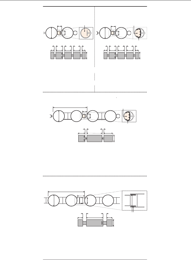
Fig. 13. Dimension and hydraulic conductivity of SPSP cutoff wall with each joint type and
outline of SP/JS-model for Case-I to Case-IV

Integrated Waste Management – Volume I
336
Furthermore, the environmental feasibilities of SPSP cutoff walls with various joints types
are evaluated by applying each converted hydraulic conductivity in the SP/JS-model.
Figure 13 shows the equivalent hydraulic conductivities of SPSP cutoff walls with various
joints types, the dimension of each joint type as well as steel pipe and the hydraulic
conductivity of each joint type. In the evaluation of the environmental feasibilities on SPSP
cutoff walls considering various joint geometries and performance levels, the SPSP cutoff
walls with the following four joint types are applied to the SP/JS-model.
Case-I: SPSP cutoff wall with the P-T joint
Case-II: SPSP cutoff wall with the improved P-T joint
Case-III: H-jointed SPSP cutoff wall with the improved P-T joint
Case-IV: H-jointed SPSP cutoff wall with the H-H joint
Figure 13 shows also the outline of the SP/JS-model for Case-I to Case-IV. Joint sections of
width 0.25 m and steel pipes of diameter 1 m were used in Case-I and Case-II, whereas joint
sections of widths 0.25 m and 0.5 m were used in Case-III and Case-IV, respectively, along
with H-jointed steel pipes of diameter 2.25 m (Oki et al., 2003; Inazumi et al., 2005, 2006).
Table 1 shows the seepage, advection and dispersion properties assigned to each
composition layer
The assumed hydraulic conductivities of the joint sections were 1.3×10
-6
cm/s in Case-I,
1.3×10
-8
cm/s in Case-II and Case-III and 1.8×10
-9
cm/s in Case-IV.
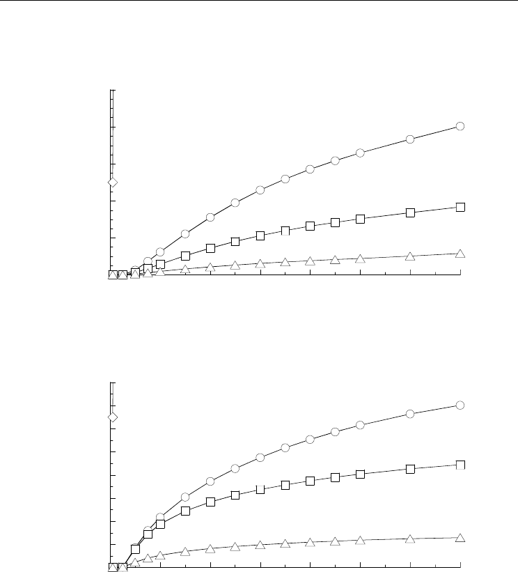
Figure 14 shows the total quantities of toxic substances leaked from the SPSP cutoff wall
onto the sea side with respect to the elapsed time for Case-I to Case-IV. The relationships
between the elapsed time and the highest concentration of toxic substances leaked from the
SPSP cutoff wall onto the sea side for Case-I to Case-IV are shown in Fig. 15. Figure 16
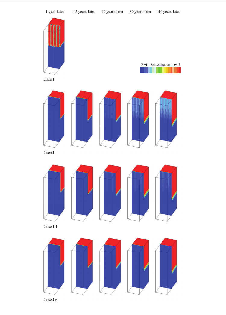
shows the distribution of the concentration of toxic substances leaking out from the waste
layer, that is, the contamination source, in Case-I to Case-IV. This distribution in Fig. 16 is
expressed from the sea side of the SPSP cutoff wall in order to facilitate a comparison among
Case-I to Case-IV with regard to the leakage of the toxic substance to outside the coastal
landfill.
The times required for the concentration levels on the sea side to exceed C=0.1 were less
than 1 year and 70 years for Case-I and the Case-II, respectively (see Fig. 15). In Case-III and
Case-IV, the leakage of toxic substances in excess of environmental standard value (C=0.1)
was not confirmed, even for durations upto 140 years. In Case-I and Case-II, the hydraulic
conductivities of the joint sections are different, although the arrangement intervals of the
joint sections are the same; thus it has been proven that low-hydraulic conductivity joint
sections in SPSP cutoff walls significantly contribute toward increasing the leachate-
containment effect. In addition, the sparser arrangement of joint sections represented in
Case-III reduces the total quantity of toxic substances leaked from the SPSP cutoff wall onto
the sea side to half that in Case-II (see Fig. 14). Consequently, the leachate leaked to the
outside of the coastal landfill sites is reduced by the low hydraulic conductivity as well as
the sparser arrangement of joint sections in the SPSP cutoff wall, thus, significantly
improving the leachate-containment effect.
The H-jointed SPSP cutoff wall with H-H joints (Case-IV) most efficiently achieves low
hydraulic conductivity with a sparser arrangement of joint sections. The leakage of leachates
in Case-IV can be traced to the lower reaches of the cutoff wall, occurring via the clay
deposit layer, which is one of the bottom cutoff barriers and is further away than other
Hydraulic Conductivity of Steel Pipe Sheet Pile Cutoff Walls at Coastal Waste Landfill Sites
337
pathways such as leakage directly through the cutoff wall (see Fig. 16). Thus, the H-jointed
SPSP cutoff wall with the H-H joint sufficiently contributes to the leachate-containment
effect of vertical cutoff barrier at coastal landfill sites.
0.0
2.0
4.0
6.0
8.0
10.0
0 20 40 60 80 100 120 140
Total quantities of
toxic substances leakage
Elapsed time (years)
Case-I Case-II
Case-III
Case-IV
(m
3
)
Fig. 14. Total quantities of toxic substances leaked from SPSP cutoff wall onto sea side with
respect to the elapsed time for Case-I to Case-IV
0.00
0.02
0.04
0.06
0.08
0.10
0.12
0.14
0.16
0 20 40 60 80 100 120 140
Highest concentration of toxic substances
leaked from SPSP cutoff wall
Elapsed time (years)
Case-I Case-II
Case-III
Case-IV
Fig. 15. Relationships between elapsed time and the highest concentration of toxic
substances leaked from SPSP cutoff wall onto sea side for Case-I to Case-IV
In this section, it was clarified that technologies that lower the hydraulic conductivities of
joint sections in SPSP cutoff walls and also facilitate the use of sparser arrangements
contribute significantly to increasing the environmental feasibilities of SPSP cutoff walls at
landfill sites. Further, the extent of the environmental feasibility of H-jointed SPSP cutoff
walls with the H-H joints among the present technical developments in SPSP cutoff walls
was shown.
Integrated Waste Management – Volume I
338
Fig. 16. Distribution of concentration of toxic substances leaking out from waste layer in
Case-I to Case-IV

Hydraulic Conductivity of Steel Pipe Sheet Pile Cutoff Walls at Coastal Waste Landfill Sites
339
4. Conclusions
An evaluation method that can express the local leakage of leachate from joint sections in
steel pipe sheet pile (SPSP) cutoff walls is discussed, in this study. In particular, the
evaluation of environmental feasibility (containment of leachates containing toxic
substances) considering a three-dimensional arrangement and hydraulic conductivity
distribution of the joint sections in the SPSP cutoff wall is compared with an evaluation that
generally uses the equivalent hydraulic conductivity.
Evaluations of the environmental feasibilities of the SPSP cutoff walls with joint sections that
have a higher hydraulic conductivity than that of the steel pipe must take into account the
local leakage of leachates containing toxic substances from the joint section; this was
possible using the SP/JS-model. Due to the local leakage into the surroundings of coastal
landfills from joint sections, contamination in excess of the environmental standard values
was confirmed to occur earlier than that predicted by the UL-model, which is the current
standard evaluation method.
It was clarified that technologies that lower the hydraulic conductivities of joint sections in
SPSP cutoff walls and also facilitate the use of sparser arrangements contribute significantly
to increasing the environmental feasibilities of SPSP cutoff walls at landfill sites. Further, the
extent of the environmental feasibility of H-jointed SPSP cutoff walls with the H-H joints
among the present technical developments in SPSP cutoff walls was shown.
5. References
Inazumi, S., Kimura, M., Nishiyama, Y., Yamamura, K., Tamura, H., & Kamon, M. (2006).
New type of hydraulic cutoff walls in coastal landfill sites from H-jointed steel pipe
sheet piles with H-H joints, Proceedings of 5th International Congress on Environmental
Geotechnics, Vol.1, pp.725-732
Inazumi, S., Kimura, M., Too, A.J.K., & Kamon, M. (2005). Performance of H-jointed steel
pipe sheet piles with H-H joint in vertical hydraulic cutoff walls, Proceedings of the
16th International Conference on Soil Mechanics and Geotechnical Engineering, Vol.4,
pp.2269-2272
Japanese Association for Steel Pipe Piles (1999). Steel Pipe Sheet Pile Foundations -Design and
Construction- (in Japanese), Japanese Association for Steel Pipe Piles
Kamon, M. & Inui, T. (2002). Geotechnical problems and solutions of controlled waste
disposal sites (in Japanese), JSCE Journal of Geotechnical Engineering, 701/III-58,
pp.1-15
Kamon, M. & Jang Y.S. (2001). Solution scenarios of geo-environmental problems,
Proceedings of the 11th Asian Regional Conference on Soil Mechanics and
Geotechnical Engineering, pp.833-852
Kamon, M., Inui, T., Katsumi, T., & Torisaki, M. (2007). Risk control in the redevelopment of
closed landfill sites from geotechnical viewpoint, Proceedings of the 7th Japanese-
Korean-French-Seminar on Geo-Environmental Engineering, pp.19-24
Kamon, M., Katsumi, T., Endo, K., Itoh, K., & Doi, A. (2001). Evaluation of the performance
of coastal waste landfill with sheet pile containment system (in Japanese),
Proceedings of the 5th Japan National Symposium on Environmental Geotechnology,
pp.279-284

Integrated Waste Management – Volume I
340
Kimura, M., Inazumi, S., Too, A.J.K., Isobe, K., Mitsuda, Y., & Nishiyama, Y. (2007).
Development and application of H-joint steel pipe sheet piles in construction of
foundations for structures, Soils and Foundations, Vol.47, No.2, pp.237-251
Nishigaki, M., Hishiya, T., Hashimoto, N., & Kohno, I. (1995). The numerical method for
saturated-unsaturated fluid density dependent groundwater flow with mass
transport (in Japanese), JSCE Journal of Geotechnical Engineering, 501/III-30, pp.135-
144
Oki, T., Torizaki, K., Kita, H., Yoshida, M., Sakaguchi, Y., & Yoshino, H. (2003). Evaluation
of impermeability performance of the vertical impermeable walls by using steel
sheet piles and steel pipe sheet piles (in Japanese), Proceedings of the 5th Japan
National Symposium on Environmental Geotechnology, pp.53-58
Shimizu, K. (2003). The latest geotechnical problems in waste landfill (in Japanese), Tsuchi-
to-Kiso, Japanese Geotechnical Society, 51/58, pp.1-4
The Landfill System & Technologies Research Association of Japan (2004). Landfills in Japan
(Rivised Edition) (in Japanese), The Journal of Waste Management
Waterfront Vitalization and Environment Research Center (2002). Design, Construction and
Management Manual for Managed Type Waste Reclamation (in Japanese), Waterfront
Vitalization and Environment Research Center