Hydroelectric Power Plants Design
Подождите немного. Документ загружается.


EM 1110-2-3006
30 Jun 94
low head power plant integrated with a dam structure and
navigation lock). Development of demand factors for unit
auxiliaries should account for the type of auxiliaries in the
plant based on trends observed at similar plants. For
instance, the governor oil pump demand for a Kaplan
turbine will be greater than that for the governor oil pump
demand for a Francis turbine of the same output rating
because of the additional hydraulic capacity needed to
operate the Kaplan turbine blades. If the plant is base
loaded, governor oil pumps will not cycle as often as
governor oil pumps in a similar plant used for automatic
generation control or peaking service.
(3) Station service systems should be designed to
anticipate load growth. Anticipated growth will depend
on a number of factors including size of the plant, loca-
tion, and whether the plant will become an administrative
center. A one- or two-unit isolated plant not suitable for
addition of more units would not be expected to experi-
ence a dramatic increase in demand for station service
power. For such a plant, a contingency for load growth
of 20 percent would be adequate. Conversely, some large
multi-purpose plants have experienced 100-percent
increases in the connected kVA loads on the station ser-
vice system over original design requirements.
(4) Capacity deficits in existing station service sys-
tems have not been caused by the designer’s inability to
predict unit auxiliary requirements, but by unforeseeable
demands to provide service for off-site facilities added to
multipurpose projects. Examples of this have been the
development of extensive maintenance and warehouse
facilities outside the power plant, or electrical require-
ments resulting from environmental protection issues such
as fish bypass equipment. The station service design
should have provisions for unanticipated load growth for
multipurpose projects with navigation locks and fish lad-
ders. For such projects, a minimum growth factor contin-
gency adder of 50 percent could be justified.
b. Auxiliary demand. Demand varies greatly with
different auxiliaries, and the selection of demand factors
requires recognition of the way various power plant
equipments will be operated. One method illustrated in
Table 7-1 assumes 1 hp as the equivalent of 1 kVA and on
lights and heaters uses the kW rating as the kVA equiva-
lent. The accuracy of the method is within the accuracy
of the assumptions of demand and diversity. The values
of demand and diversity factors correlate with trends
observed in recent years on station service loads.
Table 7-1
Estimated Station Service Load and Recommended Transformer Capacity
Connected Demand
Function Load kVA kVA
Unit Auxiliaries for 8 Units
Governor Oil Pump
Pump #1 Bus #1 8 @ 100
hp
800.00 400.00
Pump #2 Bus #2 8 @ 100
hp
800.00
Pump #3 Bus #1 4 @ 25
hp
100.00 50.00
Pump #4 Bus #2 4 @ 25
hp
100.00
Turbine Bearing Oil Pump 8 @ 1
hp
8.00 8.00
Head Cover Pump
Pump #1 Bus #1 8 @ 2
hp
16.00 16.00
Pump #2 Bus #2 8 @ 2
hp
16.00
High Bay Lights
Bus #1 7 @ 13
kW
91.00 91.00
Bus #2 7 @ 13
kW
91.00
Generator Housing Heater 8 @ 18
kW
144.00*
Transformer Cooling Water Pumps
Bus #1 2 @ 50
hp
100.00 100.00
Bus #2 2 @ 50
hp
100.00
Transformer Oil Pump
Bus #1 12 @ 2
hp
24.00 24.00
Bus #2 12 @ 2
hp
24.00
ACB Air Compressor
Bus #1 1 @ 5
hp
5.00 5.00
Bus #2 1 @ 10
hp
10.00 10.00
(Continued)
7-4

EM 1110-2-3006
30 Jun 94
Table 7-1 (Concluded)
Connected Demand
Function Load
kVA kVA
High Pressure Thrust
Bearing Oil Pump 8 @ 10
hp
80.00
Governor Air Compressor 2 @ 15
hp
30.00
General Auxiliaries
Supply to Dam 696 205
Fire Pump 25 25
HVAC-Heat Pump 380 36
Transit Oil Processor 20 20
Transit Oil Pump 10 10
Battery Charger No. 1 10 10
Battery Charger No. 2 10 0**
Elevator 25 25
Power Outlets -- 25
Draft Tube Crane 50 0
Duplex Sump Pump 15 7.5
Powerhouse Crane No. 1 100 0
Air Compressor No. 1 20 20
Air Compressor No. 2 20 0**
Filter Paper Oven 2 2
Lubricating Oil Purifier 14 14
Lubricating Oil Pump 5 0
Water Heater - 20 gal. 2 2
Water Heater - 100 gal. 5 2
Switchyard
Cable Tunnel Ventilating Fan 5 5
Power Outlets -5
Lighting 37.5 30
Air Compressors 62
Machine Shop
Largest Machine 15
Total less heating 3852.5 1164.50
Total demand with diversity factor of
75 percent 873.4 kVA
Estimated total heating load 1055.0 kVA
Estimated total demand load with heating 1928.4 kVA
Recommended size of each station service transformer 1500.0 kVA
* Not on when generator running.
** Standby
7-5
EM 1110-2-3006
30 Jun 94
Chapter 8
Control System
8-1. General
a. Scope. The control system as discussed in this
chapter deals with equipment for the control and protec-
tion of apparatus used for power generation, conversion,
and transmission. It does not include low-voltage panel-
boards and industrial control equipment as used with plant
auxiliaries. IEEE 1010 and EPRI EL-5036, Volume 10,
provide guidelines for planning and designing control
systems for hydroelectric power plants.
b. Control system components. The control system
consists primarily of a computer-based control system,
hard-wired logic or programmable logic, indicating and
recording instruments, control switches, protective relays,
and similar equipment. The greatest part of this equip-
ment should be grouped at one location to facilitate
supervision and operation of the main generating units,
transmission lines, and station auxiliaries. The grouping
of these controls at one location within the confines of the
power plant is termed “centralized control.”
c. Start-stop sequence. Each generator unit control
system should be provided with a turbine/generator start-
stop sequencing logic using a master relay located at the
generator (or unit) switchboard. The starting sequence
begins with pre-start checks of the unit, followed by start-
ing unit auxiliaries, and ends with the unit operating under
the speed-no-load condition. Manual or automatic syn-
chronizing and closure of the unit breaker can be per-
formed at the local control location. The stopping
sequence should provide for four types of unit shutdown:
protective relaying, operator’s emergency stop switch,
mechanical problems, and normal shutdown.
d. Generator switchboards. Generator switchboards
in larger power plants are located near the controlled
generator. The switchboards provide local control of the
unit. In smaller power plants, where metal-clad switch-
gear is used for switching the generator, unit control
equipment is located on auxiliary panels of the switchgear
line-up. Like the switchboards, the auxiliary panel equip-
ment provides local control of the unit.
e. Auxiliary equipment control. Large power plants
using high-voltage busing and switching or having an
adjacent switchyard as part of the development should
have control for this equipment located in the grouping
suggested in paragraph 8-1(b). Even though the
controlled equipment is remote from the plant, the equip-
ment is not “offsite.” Offsite control denotes control from
a location not resident to the plant, i.e., another plant or a
control complex at another location.
f. Control room location. In plants with a few units,
the control room location with its centralized controls
should provide ready access to the governor control cabi-
nets. In plants with ultimately four or more units, the
control room should be located near the center of the
ultimate plant or at a location allowing ready access to the
units and adjacent switchyard. The relative number and
lengths of control circuits to the units and to the switch-
yard is a factor to consider, but is secondary to consider-
ation of operating convenience. The control room should
be an elevation above maximum high water, if there is
any danger that the plant may be flooded. A decision on
the location of the control room should be reached at an
early stage of plant design, since many other features of
the plant are affected by the control room location. Con-
trol location definitions and control modes are further
described in IEEE 1010.
g. Smaller plants. In smaller power plants, where
indoor generator-voltage busing and switching are used,
hinged instrument panels on the switchgear cubicles
should be used as mounting space for main control equip-
ment. This results in the main group of control equip-
ment being located at the main switchgear location.
8-2. Control Equipment
a. General. Centralized automatic and manual con-
trol equipment should be located in the control room of
large power plants. The control console, in conjunction
with supervisory control and data acquisition (SCADA)
equipment and the status switchboard, enables the control
room operator to control the powerhouse operation.
Equipment racks housing automatic synchronizing and
centralized auxiliary equipment should be located in or
adjacent to the control room to facilitate connections with
control room equipment. If the plant is controlled from
offsite, the plant’s SCADA equipment should be located
in or adjacent to the control room.
b. Space allocation. Space allotted for control
equipment, whether in a separate control room or in the
main switchgear cubicle area, must be large enough to
accommodate the panels required for the ultimate number
of generating units and transmission lines. The space
requirement, as well as the size and location of openings
required in the floor, should be provided to the architec-
tural and structural designers to ensure proper consider-
ation in door, room, and floor slab designs.
8-1
EM 1110-2-3006
30 Jun 94
c. Cabinet construction. Generator switchboard pan-
els and doors should be 1/8-in. thick or No. 11 U.S.S.
gauge smooth select steel with angle or channel edges
bent to approximately a 1/4-in. radius. Panels should be
mounted on sills ready for powerhouse installation in
groups as large as can be shipped and moved into the
installation area. All equipment on the switchboards
should be mounted and wired at the factory, and the
boards should be shipped to the powerhouse with all
equipment in place.
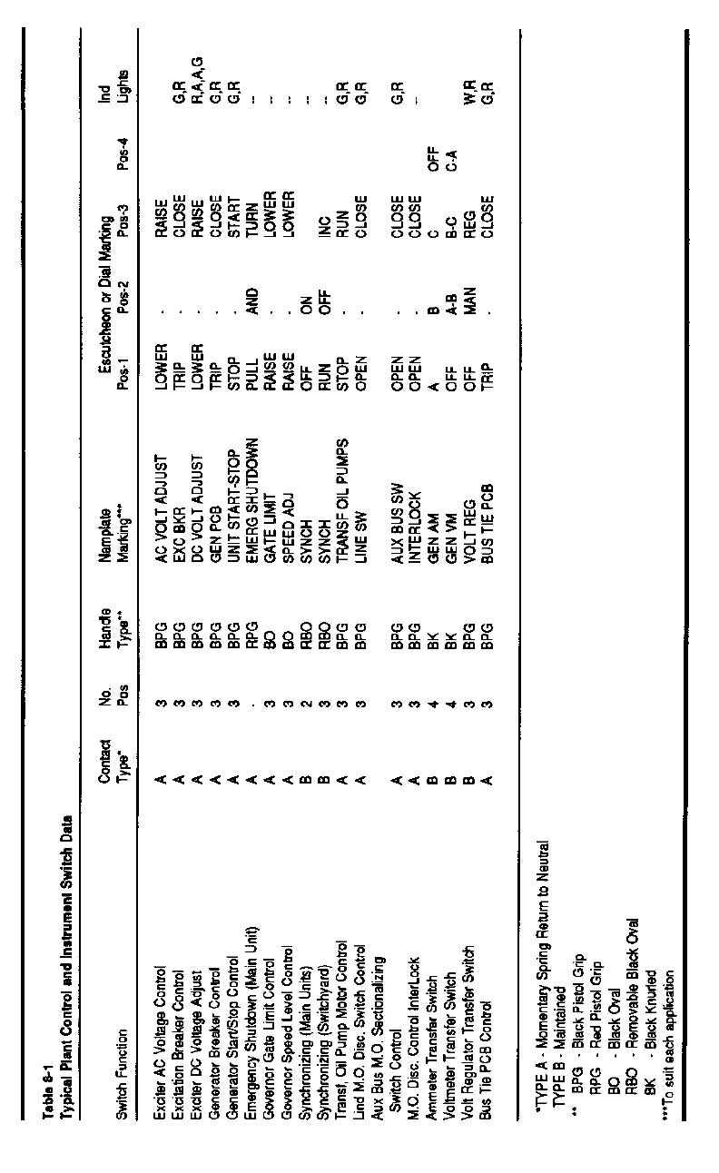
d. Equipment arrangement. The arrangement of
equipment on the control switchgear, switchboard, or
control console should be carefully planned to achieve
simplicity of design and to replicate unit control place-
ments familiar to the intended operating staff. Simplicity
of design is a definite aid to operation and tends to reduce
operating errors; therefore, the relative position of devices
should be logical and uniform. Switchboard and control
console design should be patterned after an appropriate
example to attain a degree of standardization in the
arrangement of indicating instruments and basic control
switches. Control switches should be equipped with
distinctive handles as shown in Table 8-1. Each item of
equipment should be located by consideration of its func-
tions, its relation to other items of equipment, and by its
use by the operator.
8-3. Turbine Governor
The digital governor electrical control cabinet usually is
located adjacent to the generator switchboard separate
from the actuator cabinet. The control cabinet contains
governor electronic or digital “proportional-integral-
derivative” (P-I-D) control components. The actuator
cabinet housing the power hydraulics of the governor
system is located to minimize the pressure line runs
between the turbine servomotors, the actuator, and the
governor pressure tank. For smaller capacity governors
and smaller plants, governor electronic and hydraulic
controls are all located in the governor actuator cabinet.
For mechanical considerations of turbine governors, see
EM 1110-2-4205.
8-4. Large Power Plant Control
a. General. Centralized control system equipment is
located in the control room and is interconnected to the
generator switchboards located near the units. Required
control and monitoring of all functions of the hydroelec-
tric power project are provided to the operators. The
control console with conventional control devices and
monitoring equipment in conjunction with a computer-
based data acquisition and control system (DACS), pro-
vides control and indication access to individual items of
equipment to facilitate operation, supervision, and control.
Hard-wired pushbutton switches provide for direct opera-
tor manual control of unit start-stop, breaker close (initiat-
ing automatic synchronizing), breaker trip, voltage,
loading, and gate limit raise-lower. Analog or digital
panel meters and indicating lights continuously indicate
the status of all main units, breakers, transformers, and
lines. The DACS system display monitors and keyboards
are available to operator control. The unit controls and
instruments supplement or duplicate those on the genera-
tor switchboard, and provide the control room operator
with the ability to transfer control of any selected unit or
group of units to the generator switchboard in case of
system trouble. The control console may also provide
spillway gate control, fishway control, project communi-
cations, and other project equipment control functions
when required.
b. Equipment location. Arrangement of control and
instrument switches and mimic bus should simulate the
relative order of interconnections or physical order of the
plant arrangement assisting the operator in forming a
mental picture of connections. The top of the control
console panel should be inclined to provide easier access
to the control switches and to improve console visibility.
Layouts of console visual display terminals (VDTs)
should follow applicable guidelines contained in Chap-
ter 12, “Lighting and Receptacle Systems,” to ensure good
visual acuity of the displays. Panels of the control con-
sole should be arranged for ultimate development, so that
the addition of a control panel for another generator or
another line will not disturb existing equipment.
c. Status switchboard. The status switchboard con-
tains graphic and visual indication, generator load record-
ers, station total megawatts and megavars recorders, and
other required project data displays. The status switch-
board should be located for easy observation from the
control console. The status switchboard should be a
standard modular vertical rack enclosure joined together
to form a freestanding, enclosed structure.
d. Equipment racks. Equipment racks should be
provided for mounting line relays, automatic synchroniz-
ing equipment, the common and outside annunciator
chassis, auxiliary relays, communication equipment, and
transfer trip equipment. The equipment racks should be
standard, modular, vertical rack enclosures.
8-2
EM 1110-2-3006
30 Jun 94
8-3
EM 1110-2-3006
30 Jun 94
e. SCADA equipment. The SCADA and communi-
cation equipment should be located in the general control
area.
8-5. Small Power Plant Control
a. General. Small power plants using medium-volt-
age metal-clad switchgear for generator control impose
different limitations on equipment arrangements than
arrangement limitations of generator switchboards for
local unit control. This is due to the variety of equipment
available with switchgear and, consequently, the different
possibilities for locations for major control equipment.
As noted in paragraph 8-1g, hinged instrument panels on
the main switchgear can be used for control equipment.
Where space and switchgear construction allow, it is
desirable to have hinged instrument panels on the side of
the stationary structure opposite the doors for removing
the breakers. These panels, however, provide space for
only part of the necessary control equipment, and one or
more auxiliary switchgear compartments will be required
to accommodate the remaining equipment.
b. Equipment location. Annunciator window panels,
indicating instruments, control switches, and similar
equipment should be mounted on the switchgear hinged
panels. The hinged panel for each breaker section should
be assigned to the generating unit, transmission line, or
station service transformer that the breaker serves and
only the indicating instruments, control switches, etc.,
associated with the controlled equipment mounted on the
panel. A hinged synchronizing panel should be attached
to the end switchgear cubicle.
c. Additional equipment location. Protective relays,
temperature indicators, load control equipment, and other
equipment needed at the control location and not provided
for on the switchgear panels should be mounted on the
auxiliary switchgear compartments.
d. SCADA equipment. Small power plants are fre-
quently unattended and remotely controlled from an off-
site location using SCADA equipment. The SCADA and
communication equipment should be located in the gen-
eral control area.
8-6. Protective Relays
a. General. The following discussion on protective
relays includes those devices which detect electrical faults
or abnormal operating conditions and trip circuit breakers
to isolate equipment in trouble or notify the operator
through alarm devices that corrective action is required.
The application of relays must be coordinated with the
partitioning of the electrical system by circuit breakers, so
the least amount of equipment is removed from operation
following a fault, preserving the integrity of the balance
of the plant’s electrical system.
(1) Generally, the power transmitting agency protec-
tion engineer will coordinate with the Corps of Engineers
protection engineer to recommend the functional require-
ments of the overlapping zones of protection for the main
transformers and high voltage bus and lines. The Corps
of Engineers protection engineer will determine the pro-
tection required for the station service generators and
transformers, main unit generators, main transformers, and
powerhouse bus.
(2) Electromechanical protective relays, individual
solid state protective relays, multi-function protective
relays, or some combination of these may be approved as
appropriate for the requirements. Traditional electro-
mechanical protective relays offer long life but may mal-
function when required to operate, while many less
popular designs are no longer manufactured. Individual
solid state protective relays and/or multi-function protec-
tive relays offer a single solution for many applications
plus continuous self diagnostics to alarm when unable to
function as required. Multi-function protective relays may
be cost-competitive for generator and line protection when
many individual relays would be required. When multi-
function relays are selected, limited additional backup
relays should be considered based upon safety, the cost of
equipment lost or damaged, repairs, and the energy lost
during the outage or repairs if appropriate.
(3) When the protection engineer determines that
redundancy is required, a backup protective relay with a
different design and algorithm should be provided for
reliability and security. Fully redundant protection is
rarely justified even with multi-function relay applications.
Generators, main transformers, and the high voltage bus
are normally protected with independent differential
relays.
(4) When the protective relays have been approved,
the protection engineer will provide or approve the set-
tings required for the application.
b. Main generators.
(1) The general principles of relaying practices for
the generator and its excitation system are discussed in
IEEE standards C37.101, C37.102, and C37.106.
8-4
EM 1110-2-3006
30 Jun 94
Unless otherwise stated, recommendations contained in
the above guides apply to either attended or unattended
stations.
(2) Differential relays of the high speed, percentage
differential type are usually provided to protect the stator
windings of generators rated above 1500 kVA.
(3) A high-impedance ground using a resistance-
loaded distribution transformer scheme is generally used,
thereby limiting generator primary ground fault current to
less than 25 A. A generator ground, AC overvoltage
relay with a third harmonic filter is connected across the
grounding impedance to sense zero-sequence voltage. If
the generator is sharing a GSU transformer with another
unit, a timed sequential ground relay operation to isolate
and locate generator and delta bus grounds should be
provided.
(4) Out-of-step relays are usually provided to protect
generators connected to a 500-kV power system, because
the complexity of a modern EHV power system some-
times leads to severe system frequency swings, which
cause generators to go out of step. The generator out-of-
step relays should incorporate an offset mho and angle
impedance relay system which can detect an out-of-step
condition when the swing locus passes through the gener-
ator or its transformer.
(5) Frequency relays, and under- and over-frequency
protection, are not required for hydraulic-turbine-driven
generators.
(6) Temperature relays are provided for thrust and
guide bearings as backup for resistance temperature detec-
tors and indicating thermometers with alarms. The relays
are set to operate at about 105
o
C and are connected to
shut down the unit. Shutdown at 105
o
C will not save the
babbitt on the bearing but will prevent further damage to
the machine.
c. Generator breakers.
(1) Most breaker failure relaying schemes operate on
high phase or ground currents. When a trip signal is
applied to the breaker, the breaker should open and cur-
rent flow should cease within the breaker interrupting
time. The breaker failure relay is usually applied to oper-
ate lockout relays to trip backup breakers after a time
delay based on the assumption the breaker has failed if
current flow continues after the breaker trip circuit has
been energized. These schemes do not provide adequate
protection if breaker failure occurs while current is near
zero immediately following synchronizing.
(2) Another scheme uses a breaker auxiliary contact
to detect breaker failure with fault detectors for phase
current balance, reverse power, and overcurrent relays.
Protective relay contact closing or operation of the
breaker control switch to the trip position energizes a
timing relay. If the breaker auxiliary contact does not
close within the breaker interrupting time, the timing relay
will close its contacts, enabling the phase current balance,
reverse power, and overcurrent relays to perform the
required trip functions.
(3) Some breaker control systems monitor the
breaker trip coil using a high resistance coil relay con-
nected in series with the trip coil. A time delay relay is
required to allow the breaker to open during normal trip-
ping without initiating an alarm.
(4) Provision should be made to trip generator brea-
kers when there is a loss of the breaker trip circuit DC
control power or complete loss of DC for the entire plant.
A stored energy capacitor trip device can be used to trip
the breaker in case of a loss of control power.
d. Transformer protection.
(1) Transformers or transformer banks over
1500 kVA should be protected with high-speed percent-
age-type differential relays. The basic principles involved
in transformer protection are discussed in IEEE C37.91.
(2) Separate differential relay protection for genera-
tors and transformers should be provided even on unit
installations without a generator circuit breaker. The
relays applicable for generators can be set for much closer
current balance than transformer differential relays.
(3) Auto transformers can be treated as three-
winding transformers and protected with suitable high-
speed differential relays. The tertiary winding of an
auto-transformer usually has a much lower kVA rating
than the other windings. The current transformer ratios
should be based on voltage ratios of the respective wind-
ings and all windings considered to have the same
(highest) kVA rating.
(4) Thermal relays supplement resistance tempera-
ture detectors and thermometers with alarm contacts. The
relays are set to operate when the transformer temperature
reaches a point too high for safe operation, and are
8-5
EM 1110-2-3006
30 Jun 94
connected to trip breakers unloading the transformers.
These relays are important for forced-oil water-cooled
transformers which may not have any capacity rating
without cooling water.
e. Bus protection.
(1) High-voltage switchyard buses can be protected
with bus protection, but the necessity and type of bus
protection depends on factors including bus configuration,
relay input sources, and importance of the switchyard in
the transmission system. Application of bus protection
should be coordinated with the PMA or utility operating
agency. The basic principles of bus protection operation
are discussed in IEEE C37.97.
(2) Large power plants with a complex station service
system configuration should be provided with station
service switchgear bus differential relay protection.
(3) A ground relay should be provided on the delta-
connected buses of the station service switchgear. A
voltage relay, connected to the broken-delta potential
transformer secondary windings, is usually provided to
detect grounds. A loading resistor may be placed across
the broken delta to prevent possible ferroresonance. The
ground detector usually provides only an alarm indication.
f. Feeder protection. Feeder circuits that operate at
main generator voltage and 4160-V station service feeders
should be protected with overcurrent relays having instan-
taneous trip units and a ground relay. The setting of the
ground relay should be coordinated with the setting of the
generator ground relay to prevent shutdown of a generator
due to a grounded feeder.
g. Transmission line protection. Relays for the pro-
tection of transmission lines should be selected on the
basis of dependability of operation, selectivity required for
coordination with existing relays on the interconnected
system, speed of operation required to maintain system
stability, coordinating characteristics with relays on the
other end of the line, and the PMA or utility system oper-
ating requirements. The basic principles of relaying prac-
tices are discussed in IEEE C37.95.
h. Shutdown relays. The shutdown lockout relays
stop the unit by operating shutdown equipment and trip-
ping circuit breakers. The lockout relay operations are
usually divided into two groups. A generator electrical
lockout relay, 86GX, is initiated by protective relaying or
the operator’s emergency trip switch. The generator
mechanical lockout relay, 86GM, is triggered by
mechanical troubles, such as bearing high temperatures or
low oil pressure. The unit shutdown sequence is
described in IEEE 1010.
8-7. Automatic Generation Control (AGC)
For computer-based control systems, unit load can be
controlled in accordance with an error signal developed
by digital computers periodically sampling real power
flow over the tie line, line frequency, and generator power
output. These analog signals are continuously monitored
at the load dispatch control center to obtain the plant
generation control error. The control error digital quantity
is transmitted via telemetry to each plant and allocated to
the units by the computer-based plant control system.
AGC action by the plant control system converts the
raise/lower megawatt signal into a timed relay contact
closure to the governor. The governor produces a wicket
gate open/close movement to change the generator output
power. Other modes of operation include set point con-
trol, regulating, base loaded, ramped control, manual
control, and others relative to the nature of the project and
operating philosophy. Coordination of the engineering
planning of the AGC with the marketing agency should
begin at an early stage.
8-6

EM 1110-2-3006
30 Jun 94
Chapter 9
Annunciation Systems
9-1. General
EPRI EL-5036, Volume 10, provides guidelines and
considerations in planning and designing annunciation
systems for power plants.
9-2. Audio and Visual Signals
Every power plant should be provided with an annuncia-
tion system providing both audible and visual signals in
the event of trouble or abnormal conditions.
a. Audio signals. Howler horns and intermittent
gongs are used for audible signal devices. An intermittent
gong is provided in the plant control room. Howler horns
are used in the unit area and in areas where the back-
ground noise is high (e.g., in the turbine pit) or in areas
remote from the unit (e.g., plant switchyard).
b. Visual signals. Visual signals are provided by
lighted lettered window panels of the annunciator. In
larger plants, the annunciator panel indication is
augmented by unit trouble lamps located in a readily
visible position close to the unit. The plant sequence of
events recorder (SER) is normally located in the control
room. Separate annunciators (when provided) for station
service systems and switchyards should be located on
associated control panels of the station service switchgear
or on the switchyard control panels.
9-3. Annunciator
a. General. The annunciator system should be
designed for operation on the ungrounded 125-V DC sys-
tem discussed in Chapter 11. All remote contacts used
for trouble annunciation should be electrically independent
of contacts used for other purposes so annunciator circuits
are separated from other DC circuits. Auxiliary relays
should be provided where electrically independent con-
tacts cannot otherwise be obtained. The annunciator
equipment should use solid-state logic units, lighted-
window or LED type, designed and tested for surge with-
standing capability in accordance with ANSI C37.90.1,
and manufactured in accordance with ANSI/ISA S18.1.
b. The switchboard annunciator operational sequence
should be a manual or automatic reset sequence as listed
in Table 9-1.
Automatic reset should be employed when there is either
an SER or a SCADA system backup. When the plant is
controlled and dispatched through the SCADA system of
the wheeling utility, the design reset features of the
annunciator should be coordinated to ensure proper
operation.
c. The generator switchboard is provided with
annunciator alarm points for unit emergency shutdown,
generator differential lockout, generator incomplete start,
generator or 15-kV bus ground, generator overspeed,
generator overcurrent, generator breaker low pressure, unit
control power loss, generator CO
2
power off, PT fuse
failure or undervoltage, and head cover high water.
Table 9-1
Switchboard Annunciator Operational Sequence
Auxiliary
Field Control Alarm or Repeater
Contact Pushbutton or Switch Lights Horn Contacts
Normal -- Off Off Off
Abnormal Flashing On On
Abnormal Acknowledge or Silence On Off On
Normal Reset Off Off Off
Normal Test On Off Off
9-1

EM 1110-2-3006
30 Jun 94
Certain alarm points have several trouble contacts in
parallel by equipment group. Examples include generator
excitation system trip or trouble, turbine bearing oil
trouble, generator cooling water flow, unit bearing over-
heat, generator oil level, generator stator high temperature,
and governor oil trouble.
d. The generator switchboard may be provided with
an additional annunciator for the generator step-up trans-
former and unit auxiliary equipment alarms, depending on
the plant arrangement. Generally, these alarm points are
transformer differential, transformer lockout trip, trans-
former overheat, transformer trouble, 480-V switchgear
trip, and trouble.
e. The generator excitation cubicle is provided with
an annunciator for excitation equipment alarm points for
AC regulator trip, bridge overtemperature, transformer
over temperature, regulator power supply, field overvolt-
age, maximum excitation limit, minimum excitation limit,
and volt per Hertz. Generator overvoltage, power system
stabilizer, and fan failure alarm points should be included
when required.
f. The switchboard annunciator for large power plants
should be provided with auxiliary or repeater contacts to
drive control room console remote annunciator word-
indicating lights.
g. A control console window-indicating light annun-
ciator is common to all units. One unit at a time can be
selected by use of the appropriate unit trouble status
lighted pushbutton. Visual indication is provided when
the unit switchboard annunciator is activated. The con-
sole window indicating lights are generally grouped by
switchboard annunciator points and provide essential
trouble status to the operator. Unit troubles are normally
categorized by shutdown, differential, overcurrent, cooling
water, bearing oil, unit trouble, breaker air, CO
2
dis-
charge, control power, and head cover high water. The
window indicating light annunciator provides backup for a
sequential event recorder. Unit switchboard annunciator
remote control switches to silence and reset the switch-
board annunciator should be provided on the control
console.
9-4. Sequence of Events Recorder (SER)
An SER should be provided to complement the plant
annunciation system if a SCADA system is not perform-
ing the sequence of events function. The SER provides a
time-tagged, sequenced, printed record of trouble events.
The documented record of a trouble event aids in diagnos-
ing power plant forced outages. It is designed for opera-
tion on an ungrounded 125-V DC system. All inputs
should be optically isolated and filtered for 125-V DC dry
contact change-of-state scanning. The SER minimum
resolution should be coordinated with using agencies. A
value of 2 msec is typical. When an input signal status
change occurs, the SER should automatically initiate and
produce a tabulated printed record on the data logger
identifying the event and showing the time of status
change (to the nearest millisecond). The SER should be
provided with a system clock and time synchronization
features. Each SER system should be provided with an
adequate input point capacity to monitor each alarm trou-
ble contact and provide plant breaker status necessary for
the plant operation. The alarm trouble contacts should
include IEEE 1010 requirements and project alarm points
requirements.
9-5. Trouble Annunciator Points
All of the alarm points listed in Table 9-2 below are not
required in every plant, and, conversely, requirements for
an unlisted alarm point may arise. IEEE 1010 provides
types of alarm signals transmitted to the generator annun-
ciator from the generator, excitation system, generator
terminal cabinet, generator breaker, step-up transformer,
turbine, and governor, which are listed in Table 9-2.
Table 9-2
Alarm Signals Transmitted to the Generator Annunciator
Generator Switchboard Annunciator Points
Signal Description
86GX & 86GT Unit Emergency Shutdown
87GX Generator Differential Shutdown
48TDC Generator Incomplete Start
64X Generator or 15-
kV
Bus Ground
12G Generator Overspeed
51GAR Generator Overcurrent
63 Generator Breaker Low Pressure
(Continued)
9-2