Heywood J.B. Internal Combustion Engines Fundamentals
Подождите немного. Документ загружается.

510
INTERNAL
COMBUSTION
ENGINE
FUNDAMENTALS
COMBUSnON
IN
COMPRESSION-IGNITION
ENGINES
511
fuel, respectively,? then dQ/dt becomes the difference between the chemical
energy or heat released by combustion of the fuel (a positive quantity) and the
heat transfer from the system (in engines, the heat transfer is from the system and
by thermodynamic convention is a negative quantity). Since ha,,
z
0,
E~.
(10.2)
becomes
dQ, dQch dQht dV dUa
------
-
dt dt dt
-Pdt+dt
The apparent net heat-release rate, dQ Jdt, which is the difference between the
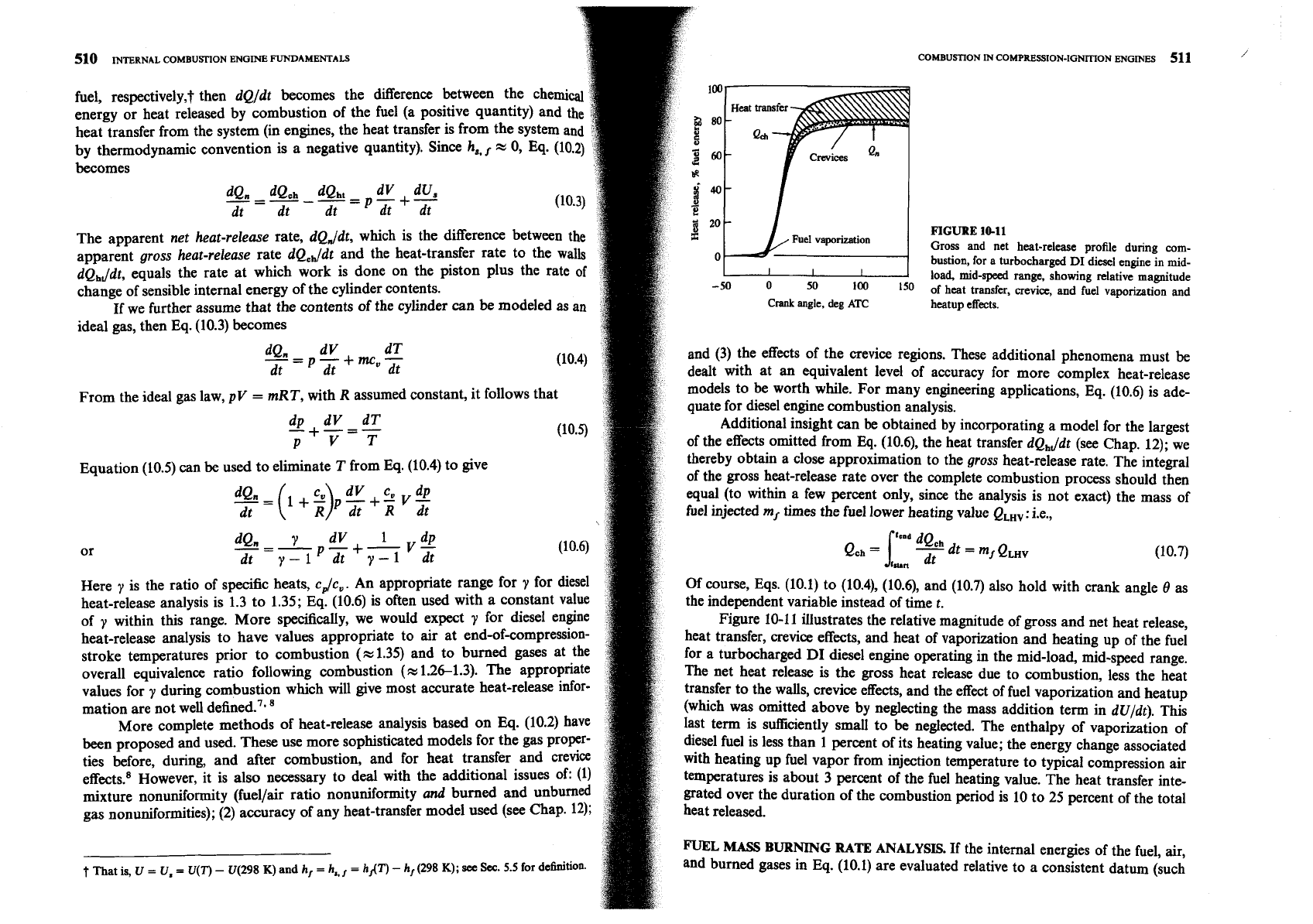
FIGURE
10-11
apparent gross heat-release rate dQ,,Jdt and the heat-transfer rate to the walls
Gross and net heat-release profile during corn-
bustion, for a turbocharged
DI
diesel engine in mid-
dQ,Jdt, equals the rate at which work is done on the piston plus the rate of
load, mid-speed range, showing relative magnitude
change of sensible internal energy of the cylinder contents.
0
of heat transfer, crevice, and fuel vaporization and
~f
we further assume that the contents of the cylinder can be modeled as
an
crank
angle,
deg
ATC
heatup effects.
ideal gas, then
Eq.
(10.3) becomes
dQ" dV
-=
dT
Pdt+mcu-
and (3) the effects of the crevice regions. These additional phenomena must
be
dt dt
dealt with at an equivalent level of accuracy for more complex heat-release
From the ideal gas law, pV
=
mRT, with
R
assumed constant, it follows that
models to be worth while. For many engineering applications, Eq. (10.6) is ade-
quate for diesel engine combustion analysis.
dp
dV dT
-+=-
Additional insight can
be
obtained by incorporating a model for the largest
PVT
of the effects omitted from Eq. (10.6), the heat transfer dQ,Jdt (see Chap. 12); we
Equation (10.5) can
be
used to eliminate
T
from Eq. (10.4) to give
thereby obtain a close approximation to the gross heat-release rate. The integral
of the gross heat-release rate over the complete combustion process should then
dV cu dp
dO.=(l+z)ph+ii~;i;
equal (to within a few percent only, since the analysis is not exact) the mass of
dt
fuel injected
m,
times the fuel lower heating value QLHv: i.e.,
-=-
dV 1 dp
dQ. 7
p-+-
or
V-
dt
y-1
dt y-1 dt (10.7)
Here 7 is the ratio of specific heats, cdc,. An appropriate range for
Y
for diesel
Of
course, Eqs. (10.1) to (10.4), (10.6), and (10.7) also hold with crank angle
8
as
heat-release analysis is 1.3 to 1.35; Eq. (10.6) is often used with a constant value
the independent variable instead of time
t.
of
within this range. More specifically, we would expect
Y
for diesel engine
Figure 10-11 illustrates the relative magnitude of gross and net heat release,
heat-release analysis to have values appropriate to air at end-of-com~ression- heat transfer, crevice effects, and heat of vaporization and heating up of the fuel
stroke temperatures prior to combustion
(z
1.35) and to burned gases at the
for a turbocharged
DI
diesel engine operating in the mid-load, mid-speed range.
overall equivalence ratio following combustion
(%
1.26-1.3). The appropriate The net heat release
is
the gross heat release due to combustion, less the heat
values for
during combustion which will give most accurate heat-release infor-
transfer to the walls, crevice effects, and the effect of fuel vaporization and heatup
mation are not well defined.'.
a
(which was omitted above by neglecting the mass addition term in dUldt). This
More complete methods of heat-release analysis based on Eq. (10.2) have
last term is sufficiently small to be neglected. The enthalpy of vaporization of
been proposed and used. These use more sophisticated models for the gas Prop-
diesel fuel is less than 1 percent of its heating value; the energy change associated
ties before, during, and after combustion, and for heat transfer and crevice
with heating up fuel vapor from injection temperature to typical compression air
effects.8 However, it is also necessary to deal with the additional issues of: (1)
temperatures is about 3 percent of the fuel heating value. The heat transfer inte-
mixture nonuniformity (fuellair ratio nonuniformity and b~rned and unburned gated over the duration of the combustion period is 10 to 25 percent of the total
gas nonunifo-ties);
(2)
accuracy of any heat-transfer model used (see Chap. 12);
FUEL
MASS
BURNING
RATE
ANALYSIS.
If the internal energies of the fuel, air,
t
That is,
u
=
U,
=
U(T)
-
U(298
K)
and
hf
=
h,,r
=
h/(T)
-
hr
(298
K);
see
Sw.
5.5
for definition.
and burned gases in Eq. (10.1) are evaluated relative to a consistent datum (such
512
INTERNAL
COMBUSTION
ENGINE
FUNDAMENTALS
COMBUSTION
IN
COMPRESSION-IGNITION ENOINES
513
as that described in Sec.
4.5.2),
then this equation can be used to obtain an
-I
8
ent
fuel mass burning rate
from cylinder pressure versus crank angle data.
such a species energy datum the "heat release" is properly
counted
for
-
7
internal energy and enthalpy terms.) Following Krieger and B~rman,~
E
can be written as
d dV dQ dm
-(mu)=
-p-+-+h
dt dt dt
dt
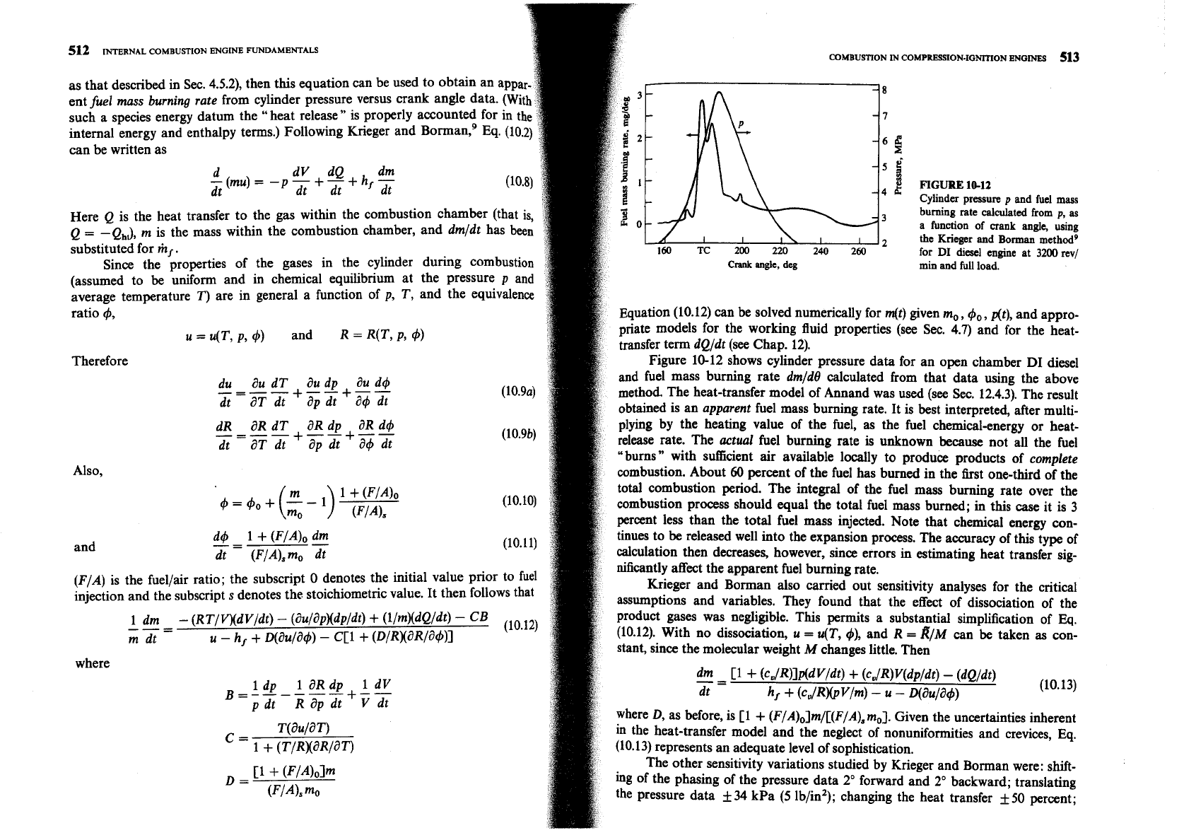
Cylinder pressure
p
and
fuel mass
Here
Q
is the heat transfer to the gas within the combustion chamber (that is,
-
burning rate
calculated
from
p,
as
Q
=
-Q,,,), m
is the mass within the combustion chamber, and
dm/dt
has been
a
function of
crank
angle, using
substituted for
m,
.
160
TC
200
220
240
260
for
DI
diesel
engme at
3200
rev/
Since the properties of the gases in the cylinder during combustion
crank
angle,
deg
min
and
full load.
(assumed to
be
uniform and in chemical equilibrium at the pressure
p
and
average temperature
T)
are in general a function of
p, T,
and the equivalence
ratio
4,
Equation
(10.12)
can be solved numerically for
m(t)
given
m,, 4,, At),
and appro-
u
=
u(T, p,
+)
and
R
=
R(T,
P,
4)
$ate models for the working fluid properties (see Sec.
4.7)
and for the heat-
transfer term
dQ/dt
(see Chap.
12).
Therefore Figure
10-12
shows cylinder pressure data for an open chamber
DI
diesel
du
au
d~
a~
dp au d4
and fuel mass burning rate
drnldtl
calculated from that data using the above
----
+--+--
dt
-
aT dt ap dt
a4
dt
method. The heat-transfer model of Annand was used (see Sec.
12.4.3).
The result
obtained is an
apparent
fuel mass burning rate. It is best interpreted, after multi-
dR aR dT aR dp aR d4
+--+--
plying by the heating value of the fuel, as the fuel chemical-energy or heat-
----
-
dt aT dt ap dt
a4
dt
release rate. The
actual
fuel burning rate is unknown because not all the fuel
"bums" with sufficient air available locally to produce products of
complete
combustion. About
60
percent of the fuel has bumed in the first one-third of the
1
+
(Fl40
total combustion period. The integral of the fuel mass burning rate over the
=
40
+
(g
-
l) (F/Als
combustion process should equal the total fuel mass burned; in this
case
it is
3
percent less than the total fuel mass injected. Note that chemical energy con-
d4
1
+
(FIA), dm
--
-
tinues to be released well into the expansion process. The accuracy of this type of
and
-
dt (F/A),m0 dt
calculation then decreases, however, since errors in estimating heat transfer sig-
nificantly affect the apparent fuel burning rate.
(F/A)
is the fuellair ratio; the subscript
0
denotes the initial value prior to fuel
Krieger and Borman also camed out sensitivity analyses for the critical
injection and the subscript
s
denotes the stoichiometric value. It then follows that
assumptions and variables. They found that the effect of dissociation of the
1
dm
-
(RT/VxdV/dt)
-
(au/apXdp/dt)
+
(llmXdQ/dt)
-
CB
(lo.1q
product gases was negligible. This permits a substantial simplification of
Eq.
---
-
rn
dt
-
h,
+
o(aula4)
-
cc1+
~D/RX~R/W)I
(10.12).
With no dissociation,
u
=
u(T,
4),
and
R
=
RIM
can be taken as con-
stant, since the molecular weight
M
changes little. Then
where
dm
C1
f
(cD/R)lddv/dt)
+
(cQ/R)Wp/dt)
-
(dQldf)
(lo.l3l
idp
1
a~dp
1
dl/
-=
B=------+--
h,
+
(C
JRX~VI~)
-
u
-
o(a~/a+)
dt
R
ap dt
v
dt
where
D,
as before, is
C1
+
(F/A)olm/[(F/A), m,].
Given the uncertainties inherent
T(au/aT)
C=
in the heat-transfer model and the neglect of nonuniformities and crevices, Eq.
1
+
(TIRXaRlaT) (10.13)
represents an adequate level of sophistication.
C1
+
(FIA)olm
The other sensitivity variations studied by Krieger and Borman were: shift-
D
=
ing of the phasing of the pressure data
2"
forward and
2"
backward; translating
VIA), mo
the pressure data
f
34
kPa
(5
lb/in2); changing the heat transfer
+50
percent;
Also,
mlmin
mg fuel
2500 16.5
1500 15.0
1035 15.8
$
200
Crank
angle, deg
(a)
Crank
angle, deg
(b)
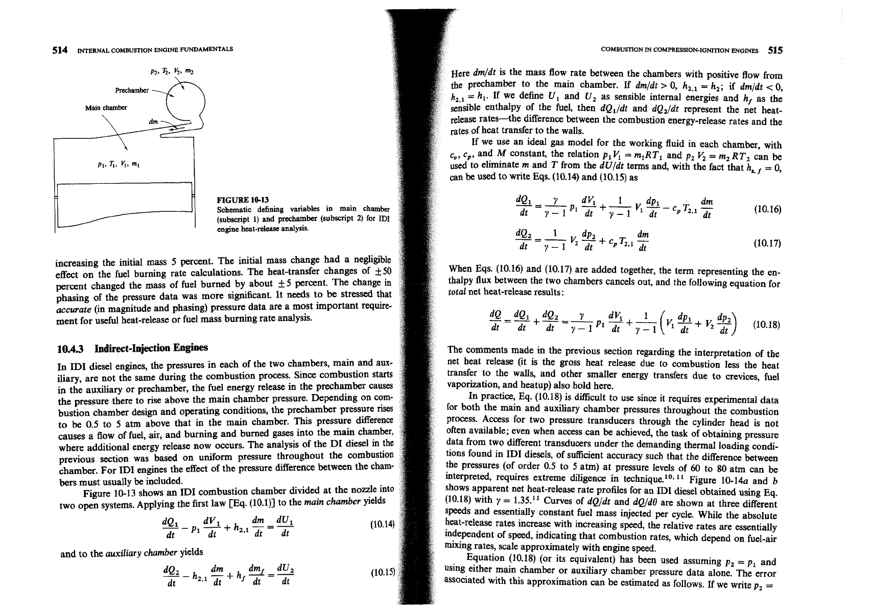
FIGURE
10-14
COMBUSTION
IN
COMPRESSION-IGNITION
ENGINES 517
1.2
0.8
P
6
0.4
I
I
0
-
-
-
I
I
-40 0 40
80
120
-40
0
40
80 120
0.06
-
1320
mlmin
1
2800
revlmin
0.04
-
Caiculated net heat-release-rate profiles for
ID1
diesel engine at constant load
(0.29
5
4
i;
0.32).
(a)
Heat-release rate in kilowatts.
(b)
Heat-release rate in joules
per
degree."
S
6i
om
-
p,
+
Ap then Eq. (10.18) becomes
I
I
0
I
32-2
J
-
dV1 Vi
+
v2
PI
v2
~(AP)
-40 0 40
80
120
Pldt+y--ldt 7-1 dt
-40
0
40 80 120
dt 7-1
Crank
angle, deg
Crank
angle, deg
If the last term is omitted, Eq. (10.19) is identical to
Eq.
(10.6) derived for the
DI
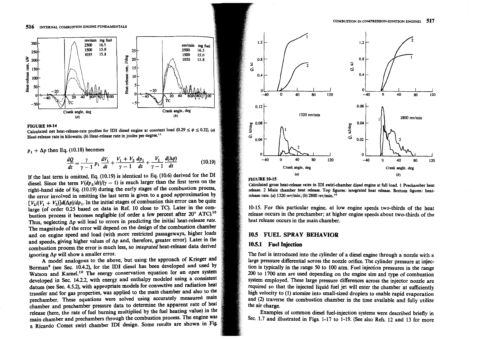
FIGURE
10-15
(a)
(b)
diesel. Since the term V(dp,/dt)/(y
-
1) is much larger than the first term on the
Calculated gross heat-release rates in
Il)I
swirl-chamber diesel enpine at
full
load.
1
prechamber heat
right-hand side of
Eq.
(10.19) during the early stages of the combustion process,
release.
2
Main chamber heat relcaec. Top figures: integrated heat release. httorn figures: heat-
the error involved in omitting the last term is given to a good approximation by
retease
rate.
(a)
1320
rev/min;
(b) 2800
rev/min.1•‹
[V2/(Vl
+
V,)]d(Ap)/dp,. In the initial stages of combustion this error can be quite
large (of order 0.25 based on data in Ref. 10 close to TC). Later in the corn-
10-15. For this particular engine, at low engine speeds two-thirds of the heat
bustion process it becomes negligible (of order a few percent after
20"
ATC)."
release Occurs in the prechamber; at higher engine speeds about two-thirds of the
Thus, neglecting Ap will lead to errors in predicting the initial heat-release rate. heat release occurs in the main chamber.
The magnitude of the error will depend on the design of the combustion chamber
and on engine speed and load (with more restricted passageways, higher loads
105
FUEL
SPRAY
BEHAVIOR
and speeds, giving higher values of Ap and, therefore, greater error). Later
in
the
combustion process the error is much less, so integrated heat-release data derived
105.1
Fuel
Injection
ignoring Ap will show a smaller error. The fuel is introduced into the cylinder of a diesel engine through a nozzle with a
A
model analogous to the above, but using the approach of Krieger
and
large Pressure differential across the nozzle orifice. The cylinder pressure at injec-
orm man^
(see Sec. 10.4.2), for the ID1 diesel has been developed and used by
tion is t~~ically in the range 50 to 100 atm. Fuel injection pressures in the range
Watson and ~ame1.l' The energy conservation equation for an open system
200
to 1700 atm are used depending on the engine size and type of combustion
developed in Sec. 14.2.2, with energy and enthalpy modeled using a consistent
system employed. These large pressure differences across the injector nozzle are
datum (see Sec. 4.5.2), with appropriate models for convective and radiation heat
required so that the injected liquid fuel jet will enter the chamber at sufficiently
transfer and for gas properties, was applied to the main chamber and also to the
(1) atomize into small-sized droplets to enable rapid evaporation
prechamber. These equations were solved using accurately measured main
e the combustion chamber in the time available and fully utilize
chamber and prechamber pressure data to determine the apparent rate of heat
release (here, the rate of fuel burning multiplied by the fuel heating value) in the
Examples of common diesel fuel-injection systems were described briefly in
main chamber and prechambers through the combustion process. The engine was
Set.
1-7 and illustrated in Figs. 1-17 to 1-19. (See also Refs. 12 and 13
for
more
a Ricardo Comet swirl chamber ID1 design. Some results are shown in Fig.
518
INTERNAL
COMBUSTION
ENGI
FUNDAMENTALS
cohfBuSmON
COMPRESSION-IGNITION
ENGMES 519
extensive descriptions of diesel fuel-injection systems.) The task of the
injection system is to meter the appropriate quantity of fuel for
speed and load to each cylinder, each cycle, and inject that fuel at the appr
Delivery-valve holder
time in the cycle at the desired rate with the spray configuration required
particular combustion chamber employed. It is important that inj
and end cleanly, and avoid any secondary injections.
To accomplish this task, fuel is usually drawn from the fuel tank by
a
supply pump, and forced through a filter to the injection pump. The injection
pump sends fuel under pressure to the nozzle pipes which carry fuel to the injec-
tor nozzles located in each cylinder head. Excess fuel goes back
Figures 1-17 and 1-19 show two common versions of fuel systems u
multicylinder engines in the 20 to 100 kW per cylinder brake power ran
operate with injection pressures between about 300 and 1200 atm.
Plunger control
arm
In-line injection pumps (Fig. 1-17) are used in en
per cylinder maximum power range. They contain a pl
for each engine cylinder. Each plunger is raised by a
cam
on th
and is forced back by the plunger return spring. The plunger st
plunger fits sufficiently accurately within the barrel to
seal
without ad
sealing elements, even at high pressures and low speeds. The amount
delivered is altered by varying the
effective
plunger stroke. This is achieve
means of a control rod or rack, which moves in the pump ho
through the fuel-injection pump.14 Such pumps are driven by an auxiliary
the plunger via a ring gear or linkage lever on the control
on the engine camshaft. Also used extensively on larger engines are unit injectors
chamber above the plunger is always connected with the chamber below
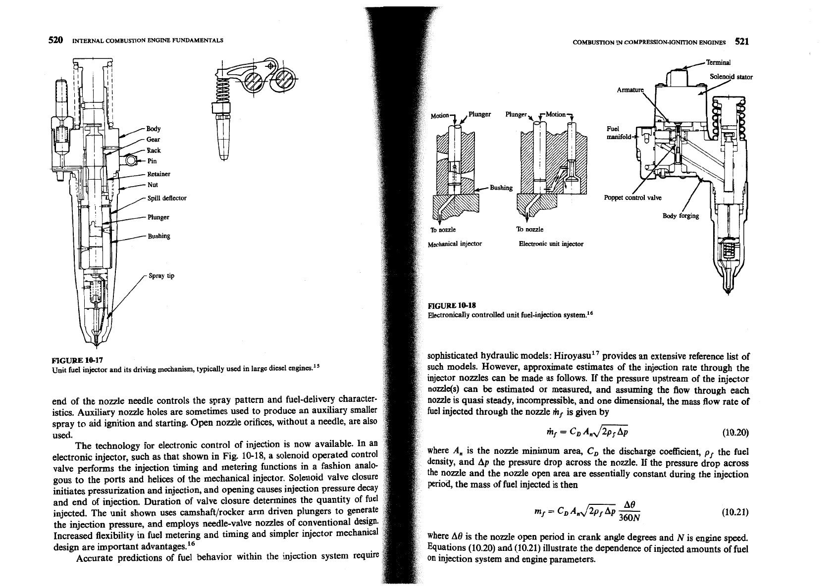
where the Pump and injector nozzle are combined into a single unit. An example
plunger helix by a vertical groove or bore in the pl
of a unit injector and its driving mechanism used on a large two-stroke cycle
the plunger helix exposes the intake port @ort
0
diesel engine is shown in Fig. 10-17. Fuel, supplied to the injector through a
plunger chamber with the suction gallery. When t
fuel-distributing manifold, enters the cavity or plunger chamber ahead
of
the
rotational position of the plunger. In the case of
a
lower
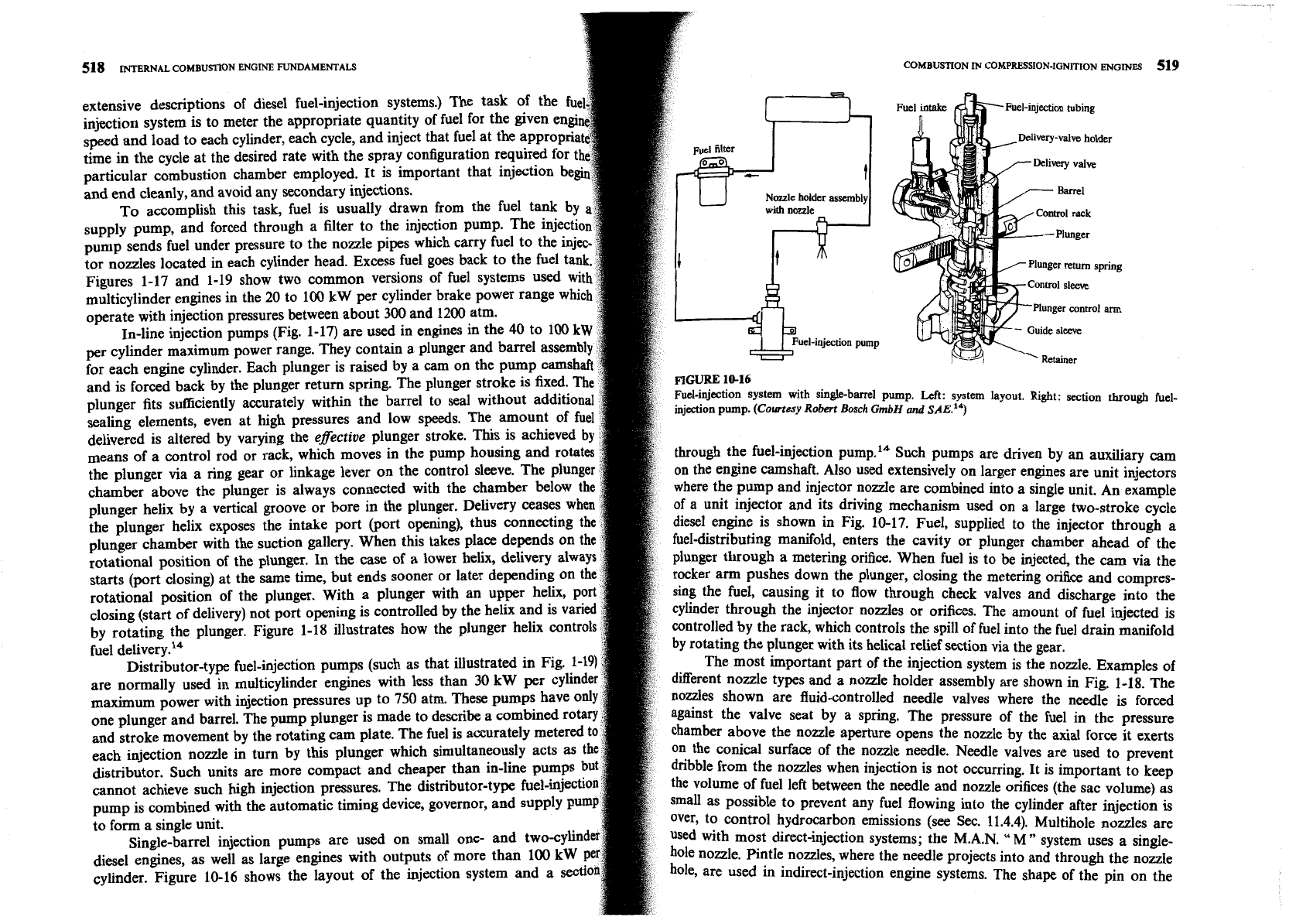
plunger through a metering orifice. When fuel is to be injected, the cam via the
starts
(port
closing) at the same time, but ends sooner or 1
rd~er arm pushes down the plunger, closing the metering orifice and compres-
rotational position of the plunger. With a pl
sing the fuel, causing it to flow through check valves and discharge into the
&sing (start of delivery) not port opening is cont
cylinder through the injector nozzles or orifices. The amount of fuel injected is
by rotating the plunger. Figure 1-18 illustrates how the
~ntrolled by the rack, which controls the spill of fuel into the fuel drain manifold
fuel delivery.14
by rotating the plunger with its helical relief section via the gear.
~istributor-type fuel-injection pumps (such as that illustrated in Fig. 1-1
The most important part of the injection system is the nozzle. Examples
of
are normally used in multicylinder engines wi
different nozzle types and a nozzle holder assembly are shown in Fig. 1-18. The
maximum power with injection pressures up to 750 atm.
nodes shown are fluid-controlled needle valves where the needle is forced
one plunger and barrel. The pump plunger is made to describe a combined rota
against the valve seat by a spring. The pressure of the fuel in the pressure
and stroke movement by the rotating
cam
plate. The fuel
chamber above the nozzle aperture opens the nozzle by the
axial
force it exerts
each injection nozzle in turn by this plunger which si
On
the conical surface of the nozzle needle. Needle valves are used to prevent
distributor. such units are more compact and cheaper than in-li
dribble from the nodes when injection is not occurring. It is important to keep
cannot achieve such
high
injection pressures. The distributor-ty
the
volume of fuel left between the needle and nozzle orifies (the sac volume) as
pump is combined with the automatic timing device, governor, and
as possible to Prevent any fuel flowing into the cylinder after injection is
to form a single unit.
Over, to control hydrocarbon emissions (see Sec. 11.4.4). Multihole nozzles are
Single-barrel injection pumps are used on small one-
used with most direct-injection systems; the
M.A.N.
"
M
"
system
usex
a
single-
diesel engines, as well
as
large engines with outputs of more than 100
kW
node. Pintle mxdes, where the needle projects into and through the nozzle
cylinder. Figure 10-16 shows the layout of the injection system and a
set
are used in indirectinjection engine systems. The shape of the in on the
MY
Gem
Rack
Pin
Retainer
Nut
Spill
deflector
Plunger
Bushing
520
INTERNAL COMBUSTION
ENGINE FUNDAMENTALS
OMBUSTION
IN
COMPRESSION-IGNITION
ENGINES
521
Electronic
unit
injector
ectronically controlled unit fuel-injection system.16
ovides
an
extensive reference list of
driving
mechanism, typically used in large diesel engines."
of the injection rate through the
pressure upstream of the injector
assuming the flow through each
end of the nozzle needle controls the spray pattern and fuel-delivery character-
ne dimensional,
the mass flow rate of
istics. Auxiliary nozzle holes are sometimes used to produce an auxiliary smaller
spray to aid ignition and starting. Open nozzle orifices, without a needle, are also
used.
mf
=
CD
Andm (10.20)
The technology for electronic control of injection is now available. In an
electronic injector, such as that shown in Fig. 10-18, a solenoid operated control
discharge
coefficient,
pf
the fuel
valve performs the injection timing and metering functions in a fashion analo-
nozzle.
If
the pressure drop across
gous to the ports and helices of the mechanical injector. Solenoid valve closure e nozzle and the nozzle open area are essentially constant during the injection
initiates pressurization and injection, and opening causes injection pressure decay
iod, the mass of fuel injected is then
and end of injection. Duration of valve closure determines the quantity of fuel
injected. The unit shown uses camshaft/rocker arm driven plungers to generate
A8
my
=
CD
A~~ZG
(10.21)
the injection pressure, and employs needle-valve nozzles of conventional design.
Increased flexibility in fuel metering and timing and simpler injector mechanical
e degrees and
N
is engine speed.
design are important advantages.16
ence of injected amounts of fuel
Accurate predictions of fuel behavior within the injection system require
FIGURE
10-17
Unit fuel injector and its
COMBUSTION IN COMPRESSION-IGNITION ENGINES 523
522
IN~RNAL
COMBUSTION
ENGINE
FUNDAMENTALS
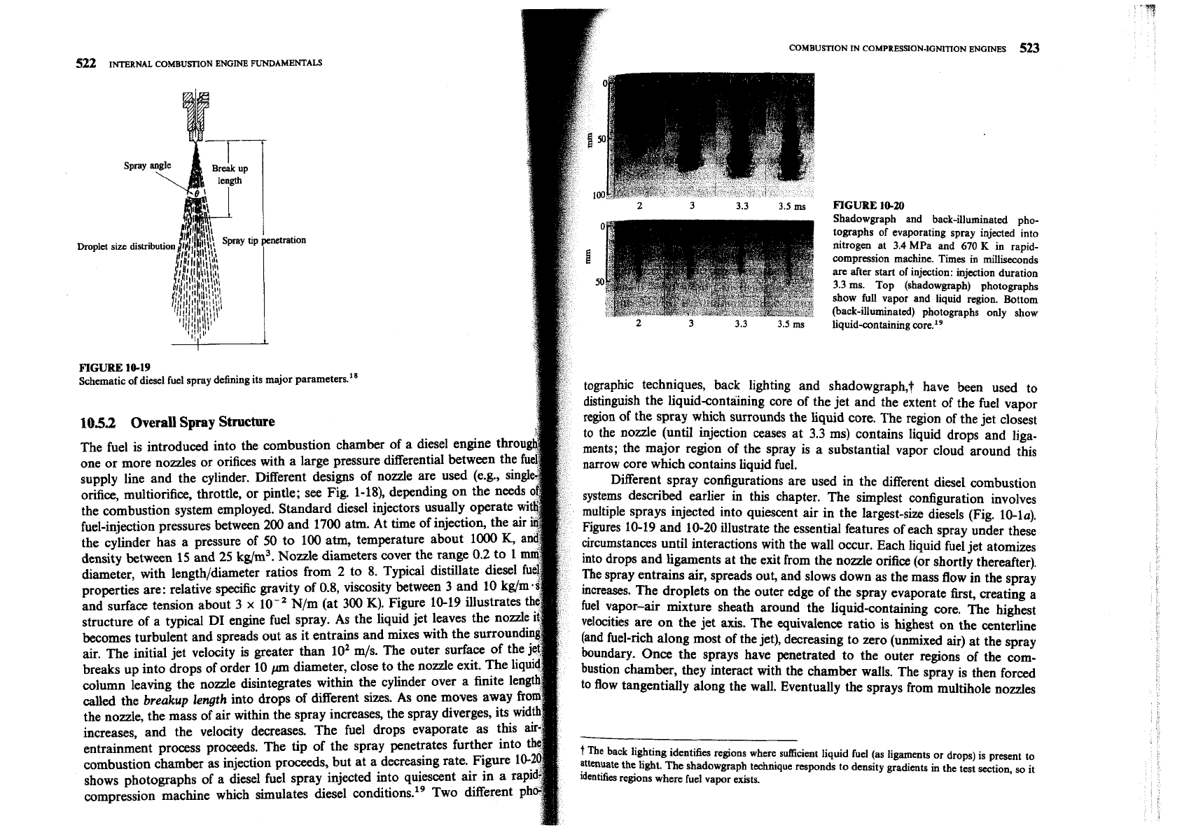
FIGURE
10-20
Shadowgraph and back-illuminated pho-
tographs of evaporating spray injected into
nitrogen at
3.4
MPa and
670
K
in rapid-
compression machine. Times in milliseconds
an?
after start of injection: injection duration
3.3
ms. Top (shadowgraph) photographs
show full vapor and liquid region. Bottom
(back-illuminated) photographs only show
liquid-containing core.lg
FIGURE
10-19
Schematic of diesel fuel spray defining its major parameters.''
tographic techniques, back lighting and shadowgraph,? have been used to
distinguish the liquid-containing core of the jet and the extent of the fuel vapor
105.2
Overall
Spray
Structure
region of the spray which surrounds the liquid core. The region of the jet closest
to the nozzle (until injection ceases at 3.3 ms) contains liquid drops and liga-
The fuel is introduced into the combustion chamber of a diesel engine tho
ments; the major region of the spray is a substantial vapor cloud around this
one or more nodes or orifices with a large pressure differential between the
narrow core which contains liquid fuel.
supply line and the cylinder. Different designs of nozzle are used (e.& sin
Different spray configurations are used in the different diesel combustion
orifice, multiorifice, throttle, or pintle; see Fig. 1-18), depending on the need
systems described earlier in this chapter. The simplest configuration involves
the combustion system employed. Standard diesel injectors usually OPer
multiple sprays injected into quiescent air in the largest-size diesels (Fig. 10-la).
fuel-injection pressures between 200 and 1700 atm. At time of injection, t
Figures 10-19 and 10-20 illustrate the essential features of each spray under these
the cylinder has a pressure of 50 to 100 atm, temperature about 10 K,
circumstances until interactions with the wall occur. Each liquid fuel jet atomizes
density between 15 and 25 kg/m3. Nozzle diameters cover the range 0.2
into drops and ligaments at the exit from the nozzle orifice (or shortly thereafter).
diameter, with length/diameter ratios from 2 to 8. Typical distillate di
The spray entrains air, spreads out, and slows down
as
the mass flow in the spray
properties are: relative
specific
gravity of 0.8, viscosity between 3 and 10
increases. The droplets on the outer edge of the spray evaporate first, creating a
and surface tension about 3
x
lo-'
N/m (at 300 K). Figure 10-19 ihst
fuel vapor-air mixture sheath around the liquid-containing core. The highest
structure of a typical
DI
engine fuel spray. As the liquid jet leaves the
velocities are on the jet axis. The equivalence ratio is highest on the centerline
becomes turbulent and spreads out as it entrains and mixes with the surroun
(and fuel-rich along most of the jet), decreasing to zero (unmixed air) at the spray
air. The initial jet velocity is greater than 10' m/s. The outer surface of th
boundary. Once the sprays have penetrated to the outer regions of the corn-
breaks up into drops of order 10
pm
diameter, close to the nozzle exit. The
h
bustion chamber, they interact with the chamber walls. The spray is then forced
column leaving the nozzle disintegrates within the cylinder over a finite len
to flow tangentially along the wall. Eventually the sprays from multihole nozzles
called the breakup length into drops of different sizes. AS One moves away
fr
the nozzle, the mass of air within the spray increases, the spray diverges, its
wi
increases, and the velocity decreases. The fuel drops evaporate as this
entrainment process proceeds. The tip of the spray penetrates further into t
The back lighting identifies regions where sufficient liquid fuel (as ligaments or drops) is present to
chamber
as
injection proceeds, but at a decreasing rate. Figure 10-
attenuate the
light.
The shadowgraph technique responds to density gradients in the test section,
so
it
shows photographs of a diesel fuel spray injected into quiescent air in
identifies regions where fuel vapor exists.
compression machine which simulates diesel conditions.lg Two different
P
524
INTERNAL COMBUmlON ENGINE FUNDAMENTALS
COMBUSTION
IN
COMPRESSION-IGNITION ENGINES
525
3
cm
2
1
0
-
1
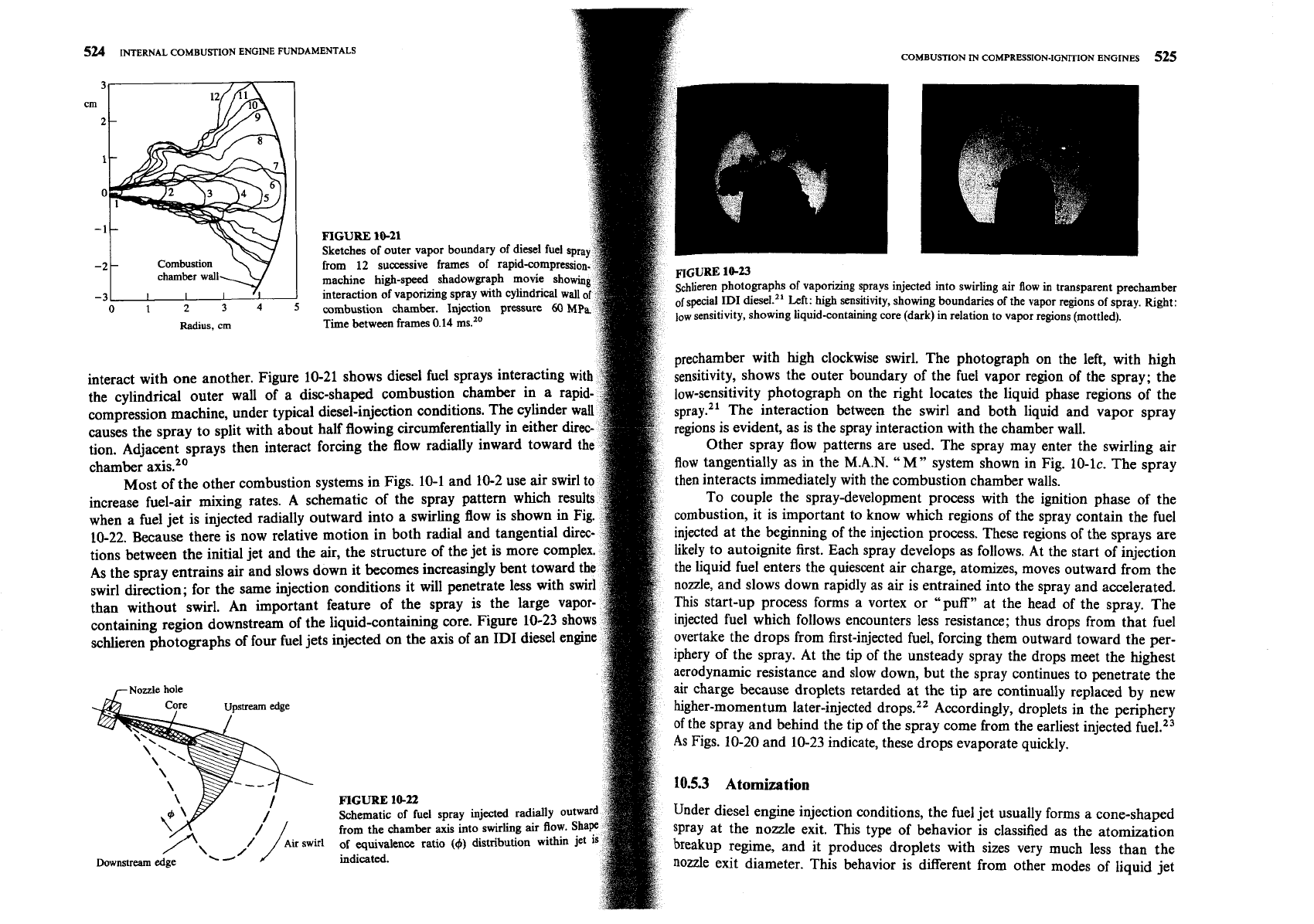
FlGURE
10-21
Sketches of outer vapor boundary of diesel fuel spra
-2
from
12
successive frames of rapidcompress
machine high-speed shadowgraph movie sho
interaction of vaporizing spray with cylindrical
wai
~chlieren photographs of vaporizing sprays injected into swirling air flow in transparent prechamber
-3
0
1
2
3
4
5
combustion chamber. Injection pressure
60
M
of
special
ID1
diesel." Left: high sensitivity, showing boundaries of the vapor regions of spray. Right:
low
sensitivity, showing liquid-containing core (dark) in relation to vapor regions (mottled).
Radius, cm
Time between frames
0.14
prechamber with high clockwise swirl. The photograph on the left, with high
interact with one another. Figure 10-21 shows diesel fuel sprays interacting wit
sensitivity, shows the outer boundary of the fuel vapor region of the spray; the
the
cylindrical outer wall of a disc-shaped combustion chamber in a ra
low-sensitivity photograph on the right locates the liquid phase regions of the
machine, under typical diesel-injection conditions. The cylinde
spray." The interaction between the swirl and both liquid and vapor spray
causes the spray to split with about half flowing circumferentially in either
regions is evident, as is the spray interaction with the chamber wall.
tion. Adjacent sprays then interact forcing the flow radially inward tow
Other spray flow patterns are used. The spray may enter the swirling air
chamber axis."
flow tangentially as in the
M.A.N.
"M"
system shown in Fig. 10-lc. The spray
Most of the other combustion systems in Figs. 10-1 and 10-2 use air swirl
then interacts immediately with the combustion chamber walls.
increase fuel-air mixing rates. A schematic of the spray pattern which resu
TO couple the spray-development process with the ignition phase of the
when a fuel jet is injected radially outward into a swirling flow is shown in Fi
combustion, it is important to know which regions of the spray contain the fuel
10-22. Because there is now relative motion in both radial and tangential
injected at the beginning of the injection process. These regions of the sprays are
tions between the initial jet and the air, the structure of the jet is more co
likely to autoignite first. Each spray develops as follows. At the start of injection
As the spray entrains air and slows down it becomes
increasingly bent towar
the liquid fuel enters the quiescent air charge, atomizes, moves outward from the
swirl direction; for the .same injection conditions it will penetrate less with s
nozzle, and slows down rapidly as air is entrained into the spray and accelerated.
than without swirl. An important feature of the spray is the large
This start-up process forms a vortex or "puff" at the head of the spray. The
containing region downstream of the liquid-containing core. Figure 10-23
injected fuel which follows encounters less resistance; thus drops from that fuel
sch1iere.n photographs of four fuel jets injected on the axis of an
ID1
diesel en@
overtake the drops from first-injected fuel, forcing them outward toward the per-
iphery of the spray. At the tip of the unsteady spray the drops meet the highest
r
Nozzle hole
:
Upstream
edge
Downsueam
age
aerodynamic resistance and slow down, but the spray continues to
the
air charge because droplets retarded at the tip are continually replaced by new
higher-momentum later-injected drops.22 Accordingly, droplets in the periphery
of the spray and behind the tip of the spray come from the earliest injected fuelz3
As
Figs. 10-20 and 10-23 indicate, these drops evaporate quickly.
10.5.3
Atomization
FIGURE
10-22
Schematic of fuel spray
injected
radially
0
Under diesel engine injection conditions, the fuel jet usually forms
a
cone-shaped
from the chamber axis into swirling air flow.
spray at the nozzle exit. This type of behavior is classified as the atomization
of
equivalence ratio
(9)
distribution within le
breakup regime, and it produces droplets with sizes very much less than the
indicated.
nozzle exit diameter. This behavior is different from other modes of liquid jet
526
INTERNAL
COMBU~TION ENGINE FUNDAMENTALS
COMBUSTION
IN
COMPRESSION-IGNITION
ENGINES
527
breakup. At low jet velocity,
in
the Rayleigh regime, breakup is due to
nun12
unstable growth of surface waves caused by surface tension and results in dr
I
0
larger than the jet diameter. As jet velocity is increased, forces due to the rela
motion of the jet and the surrounding air augment the surface tension force,
0.5
lead to drop sizes of the order of the jet diameter. This is called the first w
1
.o
induced breakup regime. A further increase in jet velocity results in brea
1.5
characterized by divergence of the jet spray after an intact or undisturbed len
2.0
downstream of the nozzle. In this second wind-induced breakup regime,
unstable growth of short-wavelength waves induced by the relative mo
between the liquid and surrounding air produces droplets whose average size
much less than the jet diameter. Further increases in jet velocity lead to break
in the atomization regime, where the breakup of the outer surface of the
occurs at, or before, the nozzle exit plane and results in droplets whose
avera
diameter is much smaller than the nozzle diameter. Aerodynamic interactions
the
liquidlgas interface appear to be one major component of the atomizatio
mechanism in this regime.".
24
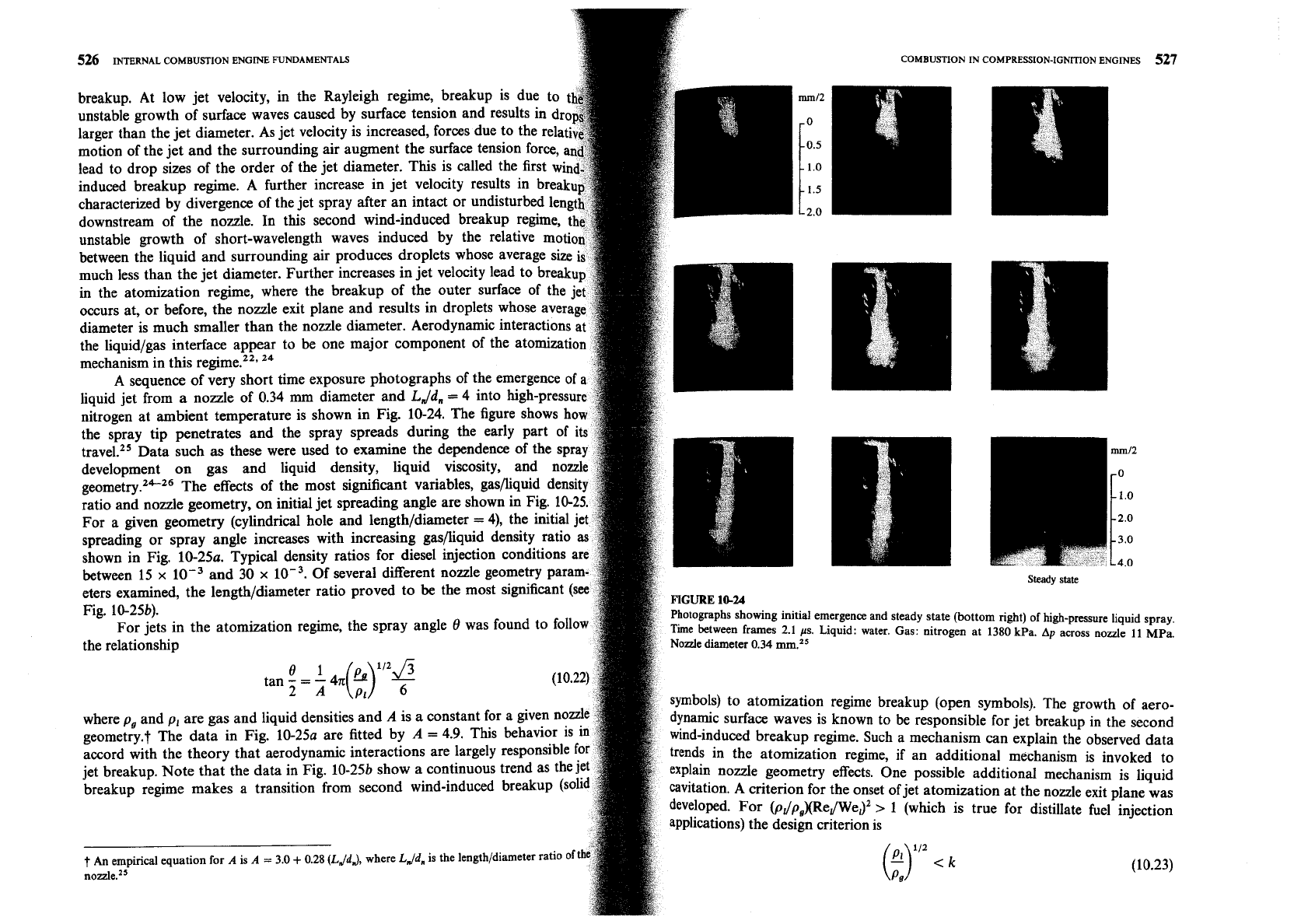
A sequence of very short time exposure photographs of the emergence of
liquid jet from a nozzle of 0.34 mm diameter and
L
Jd,
=
4 into high-press
nitrogen at ambient temperature is shown in Fig. 10-24. The figure shows
the spray tip penetrates and the spray spreads during the early par
travel.25 Data such as these were used to examine the dependence of the s
development on gas and liquid density, liquid viscosity, and
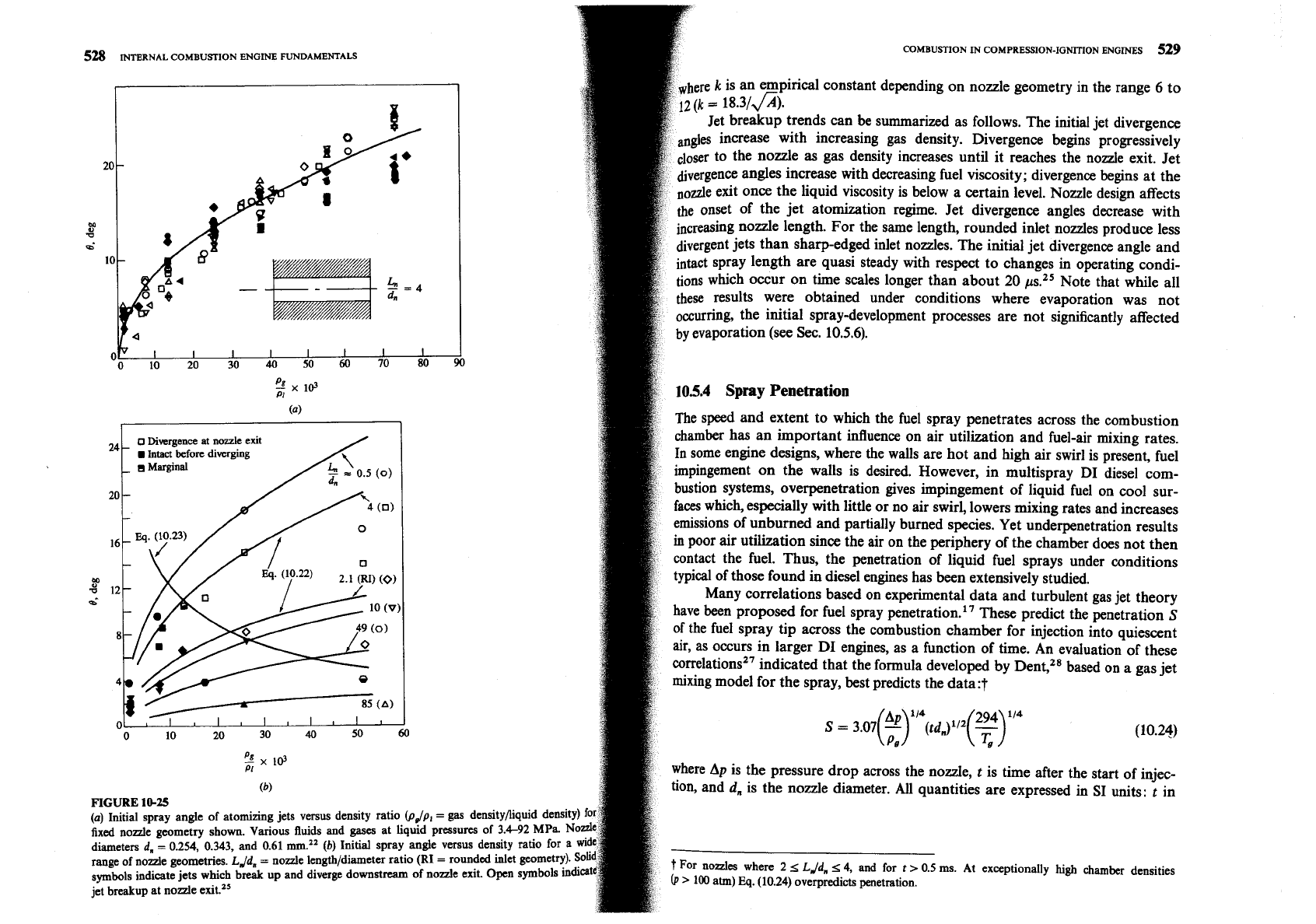
geometry.2"26 The effects of the most significant variables, gas~liquid
ratio and nozzle geometry, on initial jet spreading angle are shown in Fig.
For a given geometry (cylindrical hole and lengthldiameter
=
4), the initial
spreading or spray angle increases with increasing gaspiquid density ratio
shown in Fig. 10-25a. Typical density ratios for diesel injection conditions
between 15
x
and 30
x
Of several different nozzle geometry para
eters examined, the lengthldiameter ratio proved to be the most signifiant (s
FIGURE
1824
Fig. 10-25b).
Photographs showing initial emergence and steady state (bottom right) of high-pmsure liquid spray,
For jets in the atomization regime, the spray angle
8
was found to f0ll0
ime between frames
2.1
ps. Liquid: water. Gas: nitrogen at 1380 kpa.
A~
across
node
11
MP~.
the relationship
ode diameter 0.34 mm.z5
"
(")"'$
tan
-
=
-
411
2
A
Pl
to atomization regime breakup (open symbols). The growth of aero-
where p, and p, are gas and liquid densities and
A
is a constant for a given no
surface waves is known to be responsible for jet breakup in the second
geometry.? The data in Fig. 10-25a are fitted by
A
=
4.9. This behavior i
~~~d-induced breakup regime. Such a mechanism can explain the observed data
accord with the theory that aerodynamic interactions are largely responsible
trends in the atomization regime, if an additional mechanism is invoked to
jet breakup. Note that the data in Fig. 10-25b show a continuous trend as the
nozzle geometry effects. One possible additional mechanism is liquid
breakup regime makes a transition from second wind-induced breakup (so
cavitation.
A
criterion for the onset of jet atomization at the nozzle exit plane was
For (pJp,XReJWeJ2
>
1
(which is true for distillate fuel injection
pplications) the design criterion is
t
An empirical equation for
A
is
A
=
3.0
+
0.28
(LJdJ,
where
L
Jd,
is the length/diameter ratio of
nozzle.25
(y2
c
k
(10.23)
Steady
state
COMBUSTION
IN
COMPRESSION-IGNITION
ENGINES
529
528
INTERNAL
COMBUSTION
ENGINE
FU~AMENTALS
cal constant depending on nozzle geometry in the range
6
to
trends can be summarized as follows. The initial jet divergence
ith increasing gas density. Divergence begins progressively
e as gas density increases until it reaches the nozzle exit. Jet
ence angles increase with decreasing fuel viscosity; divergence begins at the
liquid viscosity is below a certain level. Nozzle design affects
et atomization regime. Jet divergence angles decrease with
ngth. For the same length, rounded inlet nozzles produce less
arp-edged inlet nozzles. The initial jet divergence angle and
re quasi steady with respect to changes in operating
condi-
n time scales longer than about
20
p.25
Note that while all
these results were obtained under conditions where evaporation was not
occurring, the initial spray-development processes are not significantly affected
by evaporation (see
Sec.
10.5.6).
5
x
id
PI
10.5.4
Spray
Penetration
(4
The speed and extent to which the fuel spray penetrates across the combustion
24
o
Divergence
at
nozzle
exit
chamber has an important influence on air utilization and fuel-air mixing rates.
-
Intact
before
diverging
In some engine designs, where the walls are hot and high air swirl is present, fuel
-
0
Marginal
impingement on the walls is desired. However, in multispray
DI
diesel com-
bustion systems, overpenetration gives impingement of liquid fuel on cool sur-
20
-
faces which, especially with little or no air swirl, lowers mixing rates and increases
emissions of unburned and partially burned species. Yet underpenetration results
in
poor air utilization since the air on the periphery of the chamber does not then
contact the fuel. Thus, the penetration of liquid fuel sprays under conditions
typical of those found in diesel engines has been extensively studied.
Many correlations based on experimental data and turbulent gas jet theory
have been proposed for fuel spray
penetration.17 These predict the penetration
S
of the fuel spray tip across the combustion chamber for injection into quiescent
air, as occurs in larger
DI
engines, as a function of time. An evaluation of these
correlation^^^
indicated that the formula developed by Dent?* based on a gas jet
mixing model for the spray, best predicts the data:?
IIII
20 30
40
50
60
S
=
3.07
(:)'I4
-
(td
n112(7)1'4
)
(10.24)
3
x
I@
PI
where
Ap
is the pressure drop across the nozzle,
t
is time after the start of injec-
(b)
tion, and
d,
is the nozzle diameter. All quantities are expressed in SI units:
t
in
FIGURE
10-25
t
For
nozzles
where
2
1;
L
Jd,
1;
4,
and
for
t
>
0.5
ms.
At
exceptionally
high
chamber
densities
(P
>
100
atm)
Eq.
(10.24)
overpredicts
penetration.
