Havard Devold. Oil and gas production handbook
Подождите немного. Документ загружается.

39
40
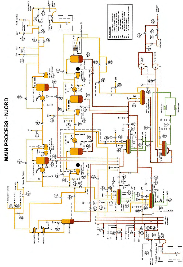
4.1 Manifolds and gathering
4.1.1 Pipelines and risers
This facility uses subsea production wells. The typical High Pressure (HP)
wellhead at the bottom right, with its Christmas tree and choke, is located on
the sea bed. A production riser (offshore) or gathering line (onshore) brings
the well flow into the manifolds. As the reservoir is produced, wells may fall
in pressure and become Low Pressure (LP) wells.
This line may include several check valves. The choke, master and wing
valves are relatively slow, therefore in the case of production shutdown, the
pressure on the first sectioning valve closed will rise to the maximum
wellhead pressure before these valves can close. The pipelines and risers
are designed with this in mind.
Short pipeline distances are not a problem, but longer distances may cause
a multiphase well flow to separate and form severe slugs - plugs of liquid
with gas in between - traveling in the pipeline. Severe slugging may upset
the separation process and cause overpressure safety shutdowns. Slugging
might also occur in the well as described earlier. Slugging can be controlled
manually by adjusting the choke, or by automatic slug controls. Furthermore,
areas of heavy condensate might form in the pipelines. At high pressure,
these plugs may freeze at normal sea temperature, e.g. if production is shut
down or with long offsets. This can be prevented by injecting ethylene glycol.
Glycol injection is not used at Njord.
The Njord floater has topside chokes for subsea wells. The diagram also
shows that Kill Fluid, essentially high specific gravity mud, can be injected
into the well before the choke.
4.1.2 Production, test and injection manifolds
Check valves allow each well to be routed into one or more of several
manifold lines. There will be at least one for each process train plus
additional manifolds for test and balancing purposes. In the diagram we
show three: test, low pressure and high pressure manifolds. The test
manifold allows one or more wells to be routed to the test separator. Since
there is only one process train, the HP and LP manifolds allow groups of HP
and LP wells to be taken to the first and second stage separators
41
respectively. The chokes are set to reduce the wellhead flow and pressure to
the desired HP and LP pressures respectively.
The desired setting for each well and which of the wells produce at HP and
LP for various production levels are defined by reservoir specialists to
ensure the optimum production and recovery rate.
4.2 Separation
As described earlier, the well-stream may consist of crude oil, gas,
condensates, water and various contaminants. The purpose of the
separators is to split the flow into desirable fractions.
4.2.1 Test separators and well test
Test separators are used to separate the well flow from one or more wells for
analysis and detailed flow measurement. In this way, the behavior of each
well under different pressure flow conditions can be defined. This normally
takes place when the well is taken into production and later at regular
intervals, typically 1-2 months and will measure the total and component flow
rates under different production conditions. Undesirable consequences such
as slugging or sand can also be determined. The separated components are
analyzed in the laboratory to determine hydrocarbon composition of the gas
oil and condensate.
Test separators can also be used to produce fuel gas for power generation
when the main process is
not running. Alternatively, a
three phase flow meter
could be used to save
weight.
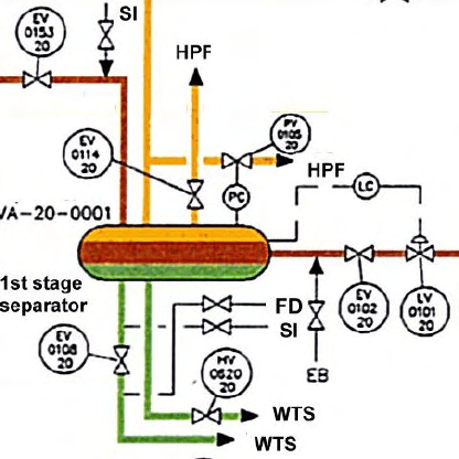
4.2.2 Production
separators
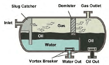
The main separators shown
here are gravity types. On
the right you see the main
components around the first
stage separator. As
mentioned before, the
production choke reduces
well pressure to the HP
manifold and first stage
42
separator to about 3-5 MPa (30-50 times atmospheric pressure). Inlet
temperature is often in the range of 100-150 degrees C. On the example
platform, the well stream is colder due to subsea wells and risers.
The pressure is often
reduced in several
stages, in this instance
three stages are used
to allow the controlled
separation of volatile
components. The idea
is to achieve maximum
liquid recovery and
stabilized oil and gas
and to separate water.
A large pressure
reduction in a single separator will cause flash vaporization leading to
instability and safety hazards.
The retention period is typically 5 minutes, allowing the gas to bubble out,
water to settle at the bottom and oil to be taken out in the middle. In this
platform the water cut (percentage water in the well flow) is almost 40%
which is quite high. In the first stage separator, the water content is typically
reduced to less than 5%.
At the crude entrance, there is a baffle slug catcher that will reduce the
effect of slugs (large gas bubbles or liquid plugs). However some turbulence
is desirable as this will release gas bubbles faster than a laminar flow.
At the end, there are barriers up to a certain level to keep back the
separated oil and water. The main control loops are the oil level control loop
(EV0101 20 above) controlling the oil flow out of the separator on the right,
and the gas pressure loop at the top.(FV0105 20 above) These loops are
operated by the Control System. An important function is also to prevent gas
blow-by which happens when a low oil level causes gas to exit via the oil
output causing high pressure downstream. There are generally many more
instruments and control devices mounted on the separator. These will be
discussed later.
The liquid outlets from the separator will be equipped with vortex breakers
to reduce disturbance on the liquid table inside. This is basically a flange trap
to break any vortex formation and ensure that only separated liquid is tapped
off and not mixed with oil or water drawn in though these vortices. Similarly
43
the gas outlets are equipped with demisters, essential filters that will
remove liquid droplets in the gas.
Emergency Valves (EV) are sectioning valves that will separate the process
components and blow-down valves, this will allows excess hydrocarbons to
be burned off in the flare. These valves are operated if critical operating
conditions are detected or on manual command, by a dedicated Emergency
Shutdown System. This might involve partial shutdown and shutdown
sequences since the flare might not be able to handle a full blow-down of all
process sections simultaneously.
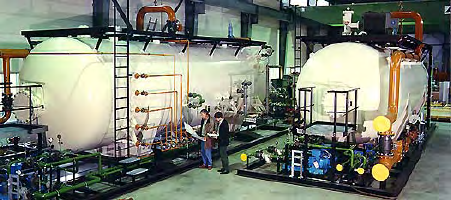
A 45,000 bpd design production with gas and 40% water cut will give about
10 cubic meters from the wellheads per minute. There also needs to be
enough capacity to handle normal slugging from wells and risers. This
means the separator has to be about 100 cubic meters, e.g. a cylinder 3
meters in diameter and 14 meters in length at the rated operating pressure.
This means a very heavy piece of equipment, typically around 50 tons for
this size, which limits the practical number of stages. Other types of
separators such as vertical separators or cyclones (centrifugal separation)
can be used to save weight, space or improve separation (see later).
There also has to be a certain minimum pressure difference between each
stage to allow satisfactory performance in the pressure and level control
loops.
Chemical additives will be discussed later.
4.2.3 Second stage separator
The second stage separator is quite similar to the first stage HP separator. In
addition to output from the first stage, it will also receive production from
wells connected to the Low Pressure manifold. The pressure is now around
1 MPa (10 atmospheres) and temperature below 100 degrees C. The water
content will be reduced to below 2%.
An oil heater could be located between the first and second stage separator
to reheat the oil/water/gas mixture. This will make it easier to separate out
water when initial water cut is high and temperature is low. The heat
exchanger is normally a tube/shell type where oil passes though tubes in a
heating medium placed inside an outer shell.
44
4.2.4 Third stage separator
The final separator here is a two-phase separator, also called a flash drum.
The pressure is now reduced to atmospheric pressure of around 100 kPa, so
that the last heavy gas components will boil out. In some processes where
the initial temperature is low, it might be necessary to heat the liquid (in a
heat exchanger) again before the flash drum to achieve good separation of
the heavy components. There are level and pressure control loops.
As an alternative, when the production is mainly gas, and remaining liquid
droplets have to be separated out, the two-phase separator can be a Knock-
Out Drum (K.O. Drum).
4.2.5 Coalescer
After the third stage separator, the oil can go to a coalescer for final removal
of water. In this unit the water content can be reduced to below 0.1%. The
coalescer is completely filled with liquid: water at the bottom and oil on top.
Internal electrodes form an electric field to break surface bonds between
conductive water and isolating oil in an oil water emulsion. The coalescer
field plates are generally steel, sometimes covered with dielectric material to
prevent short-circuits. The critical field strength in oil is in the range of 0.2 to
2 kV/cm. Field intensity and frequency as well as the coalescer grid layout
are different for different manufacturers and oil types.
4.2.6 Electrostatic desalter
If the separated oil
contains unacceptable
amounts of salts, they
can be removed in an
electrostatic desalter
(not used in the Njord
example) The salts,
which may be sodium,
calcium or magnesium
chlorides come from the reservoir water and are also dissolved in the oil.
The desalters will be placed after the first or second stage separator
depending on Gas Oil Ratio (GOR) and water cut.
Photo: Burgess Manning Europe
PLC
45
4.2.7 Water treatment
On an installation such as this, where the water cut is high, there will be a
huge amount of water produced. In our example, a water cut of 40% gives
water production of about 4000 cubic meters per day (4 million liters) that
must be cleaned before discharge to sea. Often this water contains sand
particles bound to the oil/water emulsion.
The environmental regulations in most countries are quite strict, for example,
in the North-East Atlantic the OSPAR convention limits oil in water
discharged to sea to 40 mg/liter (ppm).
It also places limits on other forms of contaminants. This still means that the
equivalent of up to one barrel of oil per day in contaminants from the above
production is discharged into the sea, but in this form, the microscopic oil
drops are broken down fast by natural bacteria.
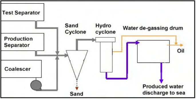
Various pieces of equipment are used. This illustration shows a typical water
treatment system. Water from the separators and coalescers first goes to a
sand cyclone, which removes most of the sand. The sand is further washed
before it is discharged.
The water then goes to a hydrocyclone, a centrifugal separator that will
remove oil drops. The hydrocyclone creates a standing vortex where oil
collects in the middle and water is forced to the side.
Finally the water is collected in the water de-gassing drum. Dispersed gas
will slowly rise to the surface and pull remaining oil droplets to the surface by
46
flotation. The surface oil film is drained, and the produced water can be
discharged to sea. Recovered oil in the water treatment system is typically
recycled to the third stage separator.
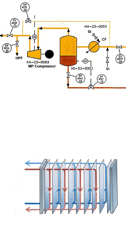
4.3 Gas treatment and compression
The gas train
consists of several
stages, each taking
gas from a suitable
pressure level in the
production
separator's gas
outlet, and from the
previous stage.
A typical stage is
shown on the right.
Incoming gas (on
the right) is first
cooled in a heat
exchanger. It then
passes through the scrubber to remove liquids and goes into the
compressor. The anti surge loop (thin orange line) and the surge valve
(UV0121 23) allow the gas to recirculate. The components are described
below.
4.3.1 Heat exchangers
For the compressor to operate efficiently, gas temperature should be low.
The lower the
temperature, the less
energy will be used to
compress the gas for the
given final pressure and
temperature. However
both gas from separators
and compressed gas are
relatively hot. When gas is
compressed, it must
remain in thermodynamic
balance, which means
that the gas pressure
47
times the volume over the temperature (PV/T) must remain constant. (PV =
nkT). This ends up as a temperature increase.
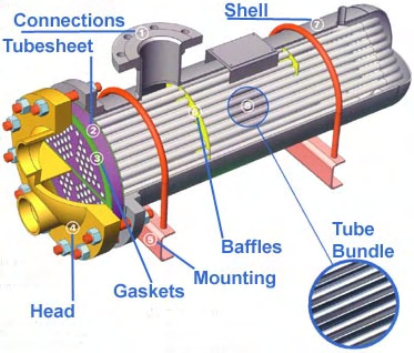
Heat exchangers of various
forms are used to cool the
gas. Plate heat exchangers
(upper picture) consist of a
number of plates where the
gas and cooling medium
pass between alternating
plates in opposing
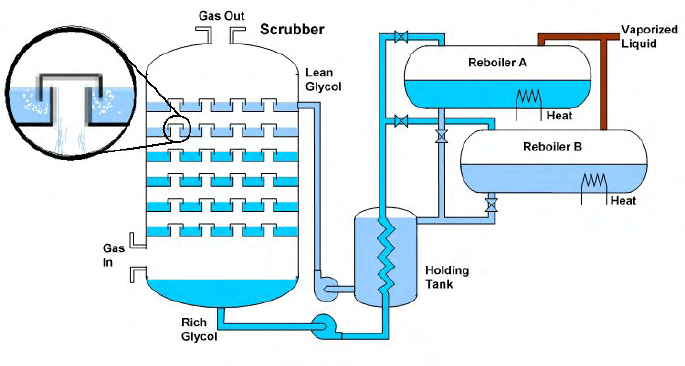
directions. Tube and shell
exchangers (next picture)
place tubes inside a shell
filled with of cooling fluid.
The cooling fluid is often
pure water with corrosion
inhibitors.
When designing the process, it is important to plan the thermal energy
balance. Heat should be conserved e.g. by using the cooling fluid from the
gas train to reheat oil in the oil train. Excess heat is dispersed e.g. by
seawater cooling. However hot seawater is extremely corrosive, so materials
with high resistance to corrosion, such as titanium must be used.
Photo: SEC
Shell and Tube Heat Exchanges
4.3.2 Scrubbers and reboilers
The separated gas may contain mist and other liquid droplets. Drops of
water and hydrocarbons also form when the gas is cooled in the heat
exchanger, and must be removed before it reaches the compressor. If liquid
droplets enter the compressor they will erode the fast rotating blades. A
scrubber is designed to remove small fractions of liquid from the gas.
There are various types of gas-drying equipment available, but the most
common suction (compressor) scrubber is based on dehydration by
absorption in Triethylene Glycol (TEG). The scrubber consists of many levels
of glycol layers.
A large number of gas traps (enlarged detail) force the gas to bubble up
through each glycol layer as it flows from the bottom up each section to the
top.
48
Processed glycol is pumped in at the top from the holding tank. It flows from
level to level against the gas flow as it spills over the edge of each trap.
During this process it absorbs liquids from the gas and comes out as rich
glycol at the bottom. The holding tank also functions as a heat exchanger for
liquid to and from the reboilers.
The glycol is recycled by removing the absorbed liquid. This is done in the
reboiler, which is filled with rich glycol and heated to boil out the liquids at
temperature of about 130-180 °C (260-350 °F) for a number of hours.
Usually there is a distillation column on the gas vent to further improve
separation of glycol and other hydrocarbons. For higher capacity, there are
often two reboilers which alternate between heating rich glycol and draining
recycled processed glycol.
On a standalone unit, the heat is supplied from a burner that uses the
recovered vaporized hydrocarbons. In other designs, heating will be a
combination of hot cooling substances from other parts of the process and
electric heaters, and recycle the hydrocarbon liquids to the third stage
separator.
4.3.3 Compressor anti surge and performance
Several types of compressors are used for gas compression, each with
different characteristics such as operating power, speed, pressure and
volume: