Groshong Richard H. 3-D Structural Geology(Second Edition)
Подождите немного. Документ загружается.

361
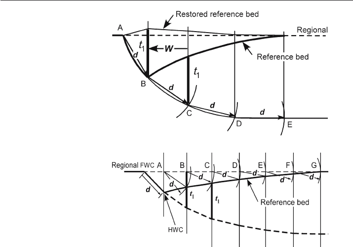
5. Sequentially from the fault cutoff, shift the vertical thickness between the regional and
the fault over one working distance in the direction of fault displacement, then move the
thickness down the working line until the top just touches the key bed (for example,
the thickness t
1
below B moves to below C). The position of the bottom of the line cor-
responds to the location of the fault. Repeat this step until the cross section is complete.
The constant fault slip model predicts the fault shape from the rollover geometry in
a rigid-rotation experiment by Chai (1994). The hangingwall is homogeneous sand
with layers of different colors, the fault is a pre
-cut shape in a rigid block, and the
extensional displacement is applied to the entire hangingwall by a flexible sheet on top of
the footwall block, a configuration developed by McClay and Ellis (1987). The critical
boundary condition in this experiment is that the flexible sheet forces the fault to main-
tain constant displacement and so the deformation mechanism is close to rigid rotation
above the listric part of the fault. Characteristic of the model is the formation of a
keystone graben between the rotated block above the listric portion of the master fault
and the translated block above the lower detachment. The graben (Fig. 11.60) repre-
sents the strain required between the two differentially displaced nearly rigid blocks.
The constant fault slip model produces a better match between the rollover shape
and the fault shape (Fig. 11.60) than any of the models described previously. The fit is
close, although not exact. The lack of a perfect fit between the predicted and observed
fault indicates that the best
-fitting model does not perfectly duplicate the mechanics of
deformation. Kinematic models are simplifications of the mechanical processes and
so a close (but not necessarily perfect) match validates the interpretation.
Fig. 11.58.
Restoration using the constant
fault slip model (after Chai
1994). d: dip separation on
fault; W: working distance
between two working lines
Fig. 11.59.
Fault shape prediction using
the constant fault slip model
(after Williams and Vann 1987).
d: dip separation on fault;
t
1
: vertical distance between
fault and regional below B;
HWC: hangingwall cutoff;
FWC: footwall cutoff; thick
dashed line: predicted fault
11.8 · Fault-Parallel Simple Shear

362 Chapter 11 · Structural Validation, Restoration, and Prediction
11.9
Pure Shear Deformation
The final kinematic model to be discussed is pure shear deformation. The pure shear
model is appropriate for the relatively uniform extension that forms a full graben.
Significantly different predictions are produced depending on the dip of the boundary
faults. The difference will be illustrated in a discussion of the Rhine graben.
11.9.1
Vertical
-Sided Graben Model
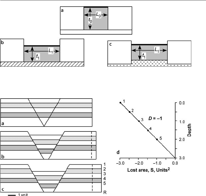
Pure-shear extension of a vertical-sided graben (Fig. 11.61a) is the model proposed by
McKenzie (1978) for the formation of an extensional basin. If this style of extension occurs
above a rigid detachment (Fig. 11.61b), the subsidence of the graben is directly related to
the amount of extension and the position of the detachment. If the extension occurs above
a thick, deformable detachment unit (Fig. 11.61c), the amount of subsidence is controlled
by isostacy and the temperature distribution (McKenzie 1978) in addition to the area
balance of the graben. In this model the strain is uniform throughout the graben. The
extension is usually calculated as the stretch, but based on the thinning, using Eq. 11.10.
11.9.2
Normal
-Fault Bounded Graben Model
In this model the region of pure shear is bounded by normal faults and a planar de-
tachment at the base (Fig. 11.62a). Extension causes the graben between the fault
boundaries to stretch horizontally and thin vertically (Fig. 11.62b,c). The area-depth
relationship provides a unique solution for the location of the lower detachment
(Fig. 11.62d) and the strain is not uniformly distributed with depth.
The area
-depth relationship, based on the deformed-state geometry of the 5 marker
horizons in Fig. 11.62c, is a straight line (Fig. 11.62d) as expected for a locally balanced
structure. The closeness of the area
-depth points to the best-fit line through the data
indicates the internal consistency of the cross section. The area
-depth line goes to zero
Fig. 11.60. Fault shapes predicted using the constant fault slip model for a sandbox experiment with
constant fault displacement (Chai 1994). The predicted fault trajectories are numbered with the layer
used to make the prediction. D: boundary displacement
363
area at the lower detachment and the slope indicates a displacement of 1 unit. A model
discussed previously (Fig. 11.18) is also a pure shear graben, but with growth sedi-
ments. Here the focus is on the internal strain in the graben.
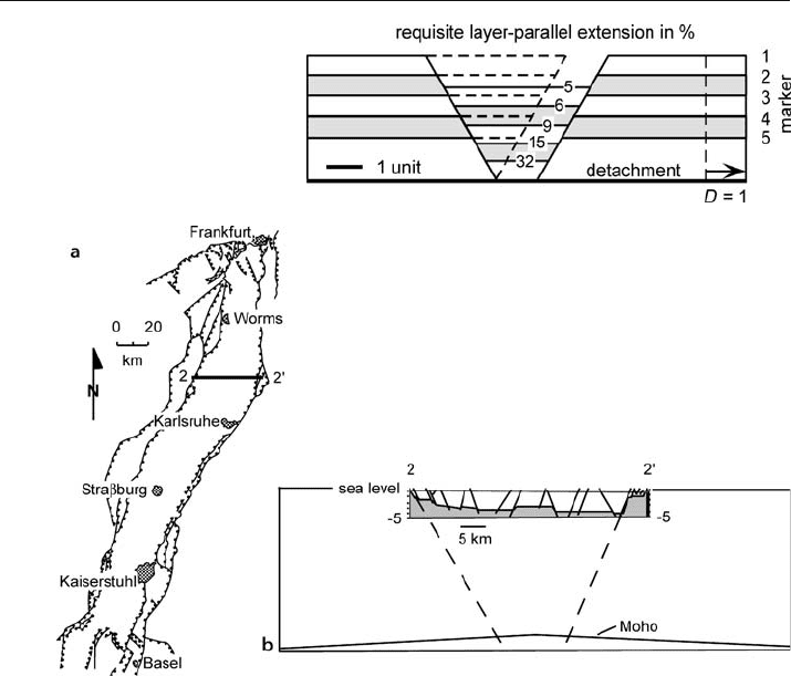
Figure 11.63 shows the magnitudes of the layer
-parallel strains for each horizon in
the full graben model of Fig. 11.62c. The strain can be determined directly from the figure
by comparing the bed lengths before and after the deformation (Eq. 11.2) as well as from
the lost areas and depth to detachment as discussed in Sect. 11.4.3.2 (Eq. 11.26 or 11.27).
Both methods give the same result. For this model the requisite strains are small in the
upper part of the graben but increase rapidly toward the lower detachment and would
approach infinity at the lower detachment because the original bed length there was zero.
Quite a different strain magnitude is obtained if the total thickness change is used to
calculate the extension (Eq. 11.10) as would be appropriate for a vertical
-sided graben.
Fig. 11.61. Vertical-sided, area-balanced graben. a Before deformation. b After deformation, subsid-
ence controlled by depth to the detachment. c After deformation, subsidence controlled by isostatic
response of the system
Fig. 11.62. Kinematic evolution of a pure shear full graben (after Groshong 1994). a Undeformed.
b Initial stage of deformation. c Final stage of deformation. d Area-depth diagram of c. Numbered points
correspond to numbered horizons in the cross section. Horizon 1 is the reference level
11.9 · Pure Shear Deformation
364 Chapter 11 · Structural Validation, Restoration, and Prediction
According to Eq. 11.11, the extension is
β
L
= 1.34 or e
L
=
β
L
– 1 = 34% extension and is
uniform with depth. This is clearly much different than the extension calculated di-
rectly from the model and shows the importance of the dip of the boundary faults.
The Rhine graben (Fig. 11.64a) provides an example of the dependence of the cal-
culated extension on the model selected. The profile (Fig. 11.64b) is from the central
area of the Rhine graben where it is relatively symmetrical, although the graben is
asymmetrical to the north and south (Brun et al. 1992; Bois 1993; Rousset et al. 1993).
The symmetry reverses across the profile area. The section to be interpreted was shown
to be sequentially restorable by rigid block displacement in Fig. 11.9, thus it is valid.
Length and area measurements were made on the preserved contact between the Per-
mian and older basement and the Triassic Buntsandstein (shown in Fig. 11.9 and 11.64b).
Because shallowly buried rocks are both brittle and weak in extension, it is mechanically
reasonable, although not certain, that nearly all of the layer
-parallel extension within the
sediments, including the Permian and older sediments of the shallow basement, occurs on
the visible faults. The extension of the top
-basement is 6.3% (Eq. 11.2), based on the bed
Fig. 11.63.
Strain in the graben of an
area-balanced model (after
Groshong 1994). The dashed
lines indicate the position of
the graben before deforma-
tion. Strain magnitudes are
in percent
Fig. 11.64. Rhine Graben (after Groshong 1996). a Index map. b Cross section 2–2' inserted in a crustal
profile. Triassic and younger sediments unshaded. The seismic refraction Moho is the base crust. (Illies
1977; Ziegler 1992; Rousset et al. 1993)
365
length of L
0
= 38.3 km, and the straight line distance across the top basement in the graben
of L
1
= 40.7 km. The Moho is at a depth of 27 km directly below the graben and is 31 km
deep outside it (Fig. 11.64b). The
β
value for the graben is 1.29 from Eq. 11.10 (e
L
= 29%),
assuming the original thickness of the crust in the Rhine graben was 31 km and the final
thickness is 24 km (27 km minus 3 km of post-Permian sediments in the graben). The drama-
tic difference in extension calculated from the two different equations is the result of the
specific pure
-shear model applied. The large value is for a vertical-sided graben and the
small value is the expected result near the top of a normal
-fault-bounded graben. Because
the Rhine graben has normal
-fault boundaries, it is reasonable to conclude that the model
of Fig. 11.63 applies to the graben and that the small strain magnitude at the top of the base-
ment does not imply a major discrepancy in the extension, but rather is the expected value.
11.10
Exercises
11.10.1
Cross
-Section Validation and Interpretation 1
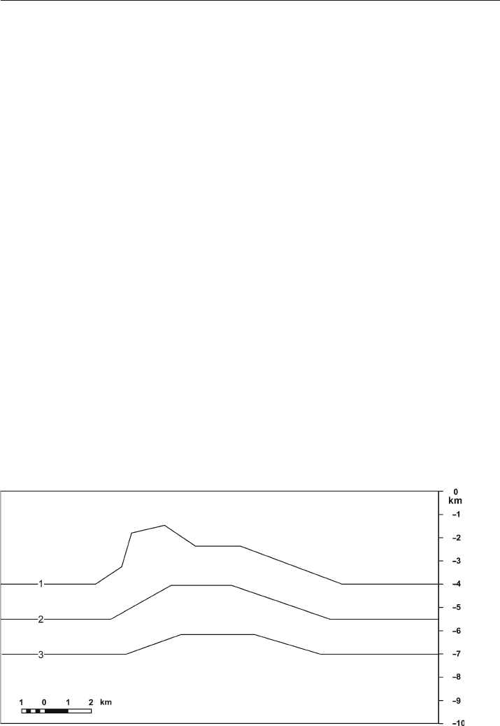
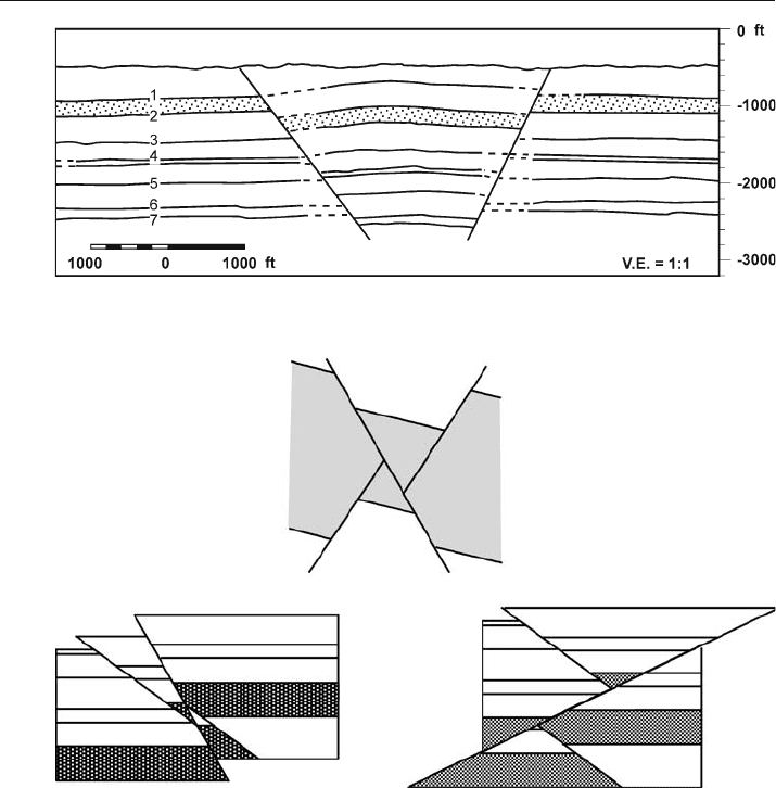
Validate (or invalidate) the cross section in Fig. 11.65. Is it length balanced? Is it area
balanced? Apply the area
-depth relationship to find the best-fitting lower detachment,
displacement, and the strain in each layer.
11.10.2
Cross-Section Validation and Interpretation 2
Validate (or invalidate) the cross section in Fig. 11.66. Is it length balanced? Is it area
balanced? Apply the area
-depth relationship to find the best-fitting lower detachment,
displacement, and the strain in each layer.
Fig. 11.65. Cross section of an anticline
11.10 · Exercises
366 Chapter 11 · Structural Validation, Restoration, and Prediction
11.10.3
Rigid
-Body Restoration
Restore the cross sections in Fig. 11.67. Why is the rigid-body method appropriate?
Are the cross sections valid? Show the structural evolution of each cross section.
11.10.4
Restoration of the Rhine Graben
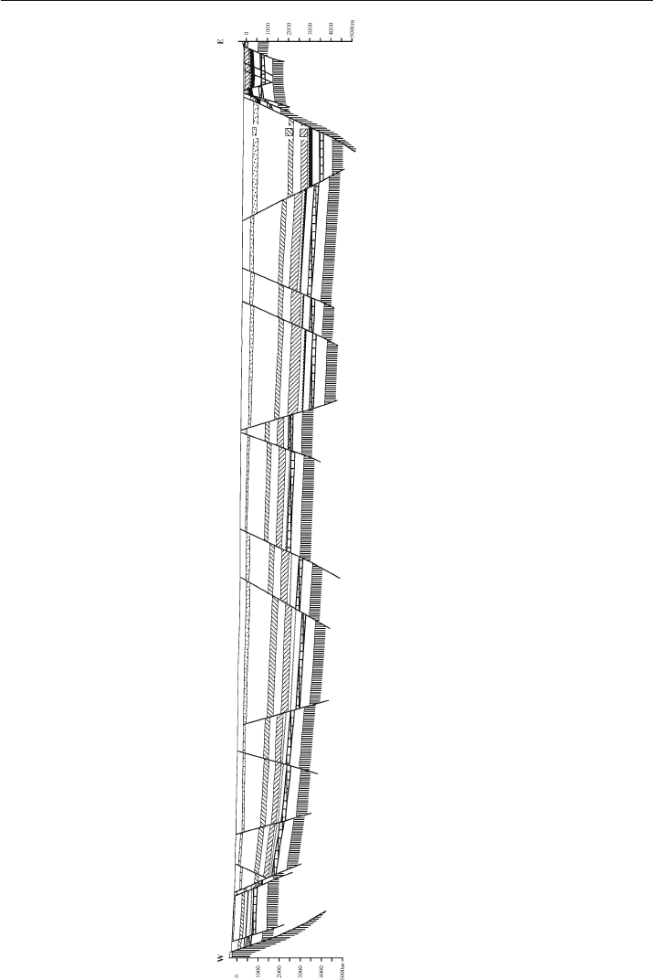
Sequentially restore the cross section of the Rhine Graben in Fig. 11.68 to the top of
the Bunte Niederroderner Schichten and the top of the Muschelkalk. What method is
most appropriate? Is the cross section valid?
Fig. 11.66. Cross section of a full graben
Fig. 11.67. Cross sections of structures formed by rigid-block displacement
367
Fig. 11.68. Cross section of the Rhine Graben. (After Doebl and Teichmüller 1979)
11.10 · Exercises
368 Chapter 11 · Structural Validation, Restoration, and Prediction
11.10.5
Flexural
-Slip Restoration 1
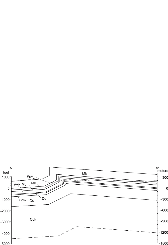
Restore the cross section of the Sequatchie anticline in Fig. 11.69. Why is the flexural-
slip method appropriate? Discuss the effect of the choice of pin line and loose line on
the result. Is the cross section valid?
11.10.6
Flexural-Slip Restoration 2
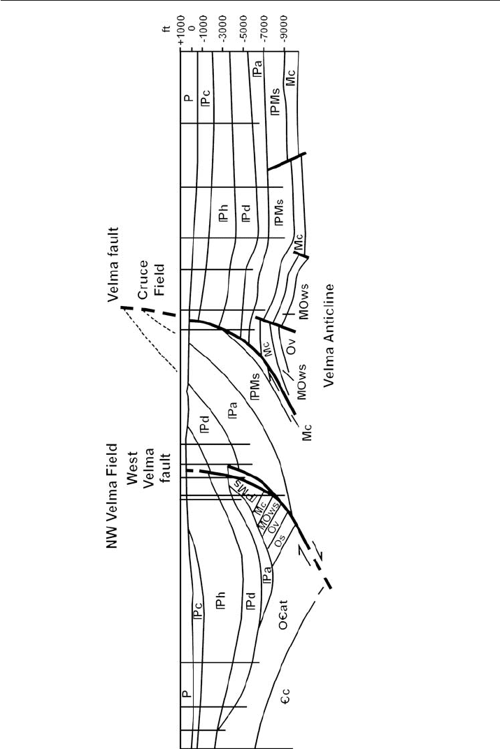
Restore the cross section of the Velma area in Fig. 11.70. Use the flexural slip technique
and preserve the original stratigraphic thickness changes. Is the cross section valid?
Discuss the origin of the major faults and their sequence of formation.
11.10.7
Flexural
-Slip Restoration 3
Restore the cross section in Fig. 11.71 by flexural slip. First it is necessary to correlate
units across the faults. Discuss the effect of the choice of pin line and loose line on
the result. Could the interpretation be questioned or improved? Is the cross section
valid?
11.10.8
Balance and Restoration
Restore the cross section of the Deer Park anticline (Fig. 11.72) by flexural slip or
area balance, as appropriate. Construct an area
-depth diagram for the entire anti-
cline. What displacement caused the structure and what displacement is present on
Fig. 11.69. Cross section of the Sequatchie anticline
369
Fig. 11.70. Cross section through the Velma area, Oklahoma. (Redrawn from Perry 1989)
11.10 · Exercises
370 Chapter 11 · Structural Validation, Restoration, and Prediction
Fig. 11.71. Cross section of a portion of the Ruhr coal district, Germany. Triangles are located on the
hangingwalls of the thrust faults. (After Drozdzewski 1983)
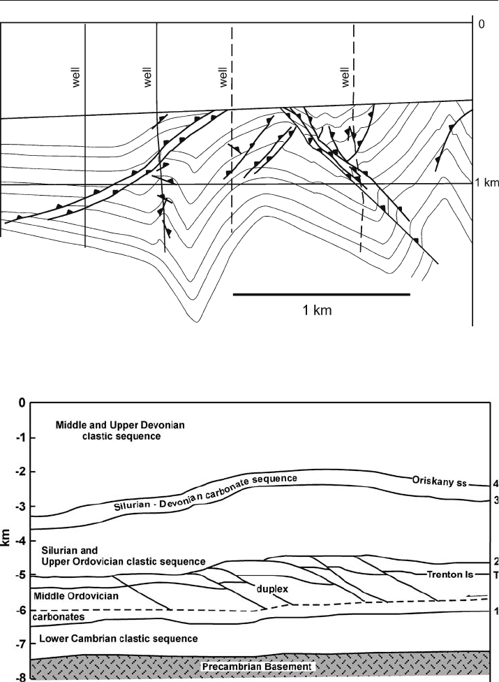
Fig. 11.72. Geological cross section across the Deer Park anticline, Appalachian Plateau fold-thrust belt,
eastern U.S. The section is depth converted from Mitra (1986) using a velocity of 5 km s
–1
. The inferred
lower detachment is the dotted line. Epard and Groshong (1995) discuss the interpretation
