Gibilisco S. Teach Yourself Electricity and Electronics
Подождите немного. Документ загружается.

Multiplying Complex Numbers
When you multiply these numbers, you should treat them as sums of number pairs, that is, as bi-
nomials. It’s easier to give the general formula than to work with specifics here. If a, b, c, and d are
real numbers (positive, negative, or zero), then:
(a + jb) (c + jd )
= ac + jad + jbc + j
2
bd
= (ac − bd ) + j(ad + bc)
Fortunately, you won’t encounter complex number multiplication problems very often in electron-
ics. Nevertheless, a working knowledge of how complex numbers multiply can help you get a solid
grasp of them.
The Complex Number Plane
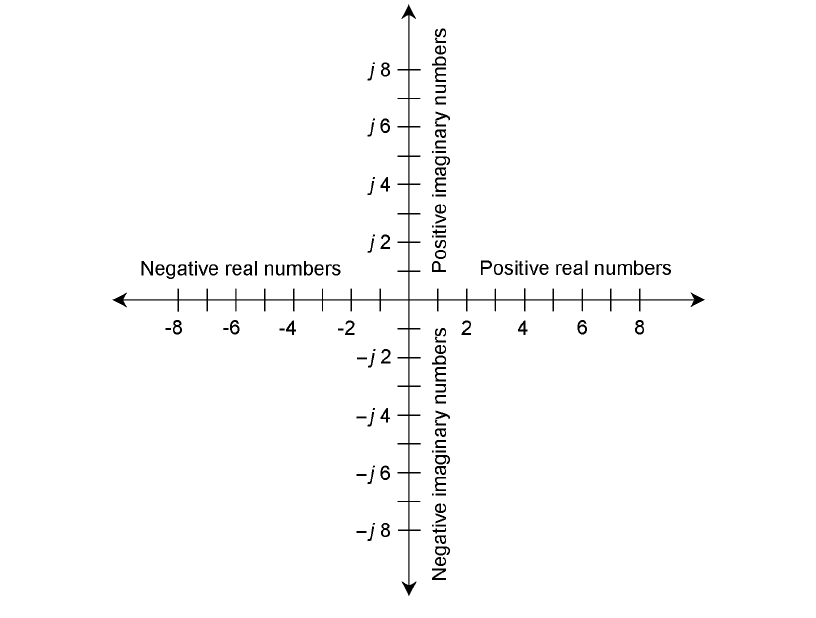
A complete complex number plane is made by taking the real and imaginary number lines and plac-
ing them together, at right angles, so that they intersect at the zero points, 0 and j0. This is shown
in Fig. 15-2. The result is a Cartesian coordinate plane, just like the ones people use to make graphs
of everyday things such as stock price versus time.
Complex Numbers 231
15-2 The complex number plane.

Complex Number Vectors
Complex numbers can also be represented as vectors. This gives each complex number a unique
magnitude and a unique direction. The magnitude is the distance of the point a + jb from the origin
0 + j0. The direction is the angle of the vector, expressed counterclockwise from the positive real-
number axis. This is shown in Fig. 15-3.
Absolute Value
The absolute value of a complex number a + jb is the length, or magnitude, of its vector in the com-
plex plane, measured from the origin (0,0) to the point (a,b).
In the case of a pure real number a + j0, the absolute value is simply the real number itself, a, if
a is positive. If a is negative, then the absolute value of a + j0 is equal to −a.
In the case of a pure imaginary number 0 + jb, the absolute value is equal to b, if b (a real num-
ber) is positive. If b is negative, the absolute value of 0 + jb is equal to −b.
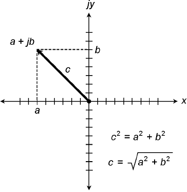
If the number a + jb is neither pure real or pure imaginary, the absolute value must be found by
using a formula. First, square both a and b. Then add them. Finally, take the square root. This is the
length, c, of the vector a + jb. The situation is illustrated in Fig. 15-4.
Problem 15-1
Find the absolute value of the complex number −22 − j0.
This is a pure real number. Actually, it is the same as −22 + j0, because j0 = 0. Therefore, the
absolute value of this complex number is −(−22) = 22.
Problem 15-2
Find the absolute value of 0 − j34.
This is a pure imaginary number. The value of b in this case is −34, because 0 − j34 = 0 +
j(−34). Therefore, the absolute value is −(−34) = 34.
232 Impedance and Admittance
15-3 Magnitude and
direction of a vector
in the complex
number plane.
Problem 15-3
Find the absolute value of 3 − j 4.
In this number, a = 3 and b =−4. Squaring both of these, and adding the results, gives us 3
2
+
(−4)
2
= 9 + 16 = 25. The square root of 25 is 5. Therefore, the absolute value of this complex num-
ber is 5.
The RX Plane
Recall the planes for resistance (R) and inductive reactance (X
L
) from Chap. 13. This is the same as
the upper-right quadrant of the complex number plane shown in Fig. 15-2. Similarly, the plane for
resistance and capacitive reactance (X
C
) is the same as the lower-right quadrant of the complex num-
ber plane. Resistances are represented by nonnegative real numbers. Reactances, whether they are
inductive (positive) or capacitive (negative), correspond to imaginary numbers.
No Negative Resistance
There is no such thing, strictly speaking, as negative resistance. You cannot have anything better
than a perfect conductor. In some cases, a supply of direct current, such as a battery, can be treated
as a negative resistance; in other cases, you can have a device that acts as if its resistance were nega-
tive under certain changing (or dynamic) conditions. But for most practical applications in the RX
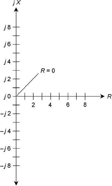
plane, the resistance value is always positive. You can remove the negative axis, along with the upper-
left and lower-left quadrants, of the complex number plane, obtaining a half plane, as shown in Fig.
15-5, and still get a complete set of coordinates for depicting complex impedances.
“Negative Inductors” and “Negative Capacitors”
Capacitive reactance, X
C
, is effectively an extension of inductive reactance, X
L
, into the realm of neg-
atives. Capacitors act like “negative inductors.” It’s equally true to say that inductors act like “nega-
tive capacitors,” because the negative of a negative number is a positive number. Reactance can vary
from extremely large negative values, through zero, to extremely large positive values.
The RX Plane 233
15-4 Calculation of absolute
value, or vector length.
Here, the vector length
is represented by c.
Vector Representation of Impedance
Any impedance R + jX can be represented by a complex number of the form a + jb. Just let R = a
and X = b. Now try to envision how the impedance vector changes as either R or X, or both, are var-
ied. If X remains constant, an increase in R causes the vector to get longer. If R remains constant and
X
L
gets larger, the vector grows longer. If R stays the same but X
C
gets larger negatively, the vector
grows longer.
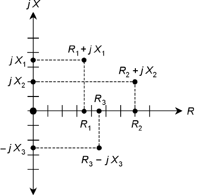
Think of the point R + jX moving around in the RX plane, and imagine where the correspon-
ding points on the axes lie. These points can be found by drawing dashed lines from the point R +
jX to the R and X axes, so that the dashed lines intersect the axes at right angles. Some examples are
shown in Fig. 15-6.
Now think of the points for R and X moving toward the right and left, or up and down, on their
axes. Imagine what happens to the point R + jX in various scenarios. This is how impedance changes
as the resistance and reactance in a circuit are varied.
Resistance is one-dimensional. Reactance is also one-dimensional. But impedance is two-
dimensional. To fully define impedance, you must render it on a two-dimensional coordinate sys-
tem such as the RX plane. The resistance and the reactance can change independently of one
another.
234 Impedance and Admittance
15-5 The complex
impedance plane, also
called the resistance-
reactance (RX ) plane.
Absolute-Value Impedance
You’ll occasionally read or hear that the “impedance” of some device or component is a certain num-
ber of ohms. For example, in audio electronics, there are “8-Ω” speakers and “600-Ω” amplifier in-
puts. How, you ask, can manufacturers quote a single number for a quantity that is two-dimensional
and needs two numbers to be completely expressed?
That’s a good question, and there are two answers. First, figures like this refer to devices that
have purely resistive impedances, also known as nonreactive impedances. Thus, the 8-Ω speaker really
has a complex impedance of 8 + j0, and the 600-Ω input circuit is designed to operate with a com-
plex impedance at, or near, 600 + j0. Second, you can talk about the length of the impedance vec-
tor (that is, the absolute value of the complex impedance), calling this a certain number of ohms. If
you talk about impedance this way, however, you are being ambiguous. There can exist an infinite
number of different vectors of any given length in the RX plane.
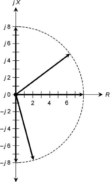
Sometimes, the uppercase italic letter Z is used in place of the word impedance in general dis-
cussions. This is what engineers mean when they say things like “Z = 50 Ω” or “Z = 300 Ω nonre-
active.” In this context, if no specific impedance is given, “Z = 8 Ω” can theoretically refer to 8 + j0,
0 + j8, 0 − j8, or any other complex impedance point on a half circle consisting of all points 8 units
from 0 + j0. This is shown in Fig. 15-7.
Problem 15-4
Name seven different complex impedances that can theoretically be meant by the expression “Z =
10 Ω.”
It’s easy name three: 0 + j10, 10 + j0, and 0 − j10. These represent pure inductance, pure resist-
ance, and pure capacitance, respectively.
A right triangle can exist having sides in a ratio of 6:8:10 units. This is true because 6
2
+ 8
2
=
10
2
. (Check it and see!) Therefore, you can have 6 + j8, 6 − j8, 8 + j6, and 8 − j6, all complex im-
pedances whose absolute value is 10.
The RX Plane 235
15-6 Some points in the
complex impedance
plane, and their
resistive and reactive
components on
the axes.
Characteristic Impedance
There is a rather exotic property of certain electronic components that you’ll sometimes hear or read
about. It is called characteristic impedance or surge impedance, and is symbolized Z
o
. It is a specifica-
tion of an important property of transmission lines. It can always be expressed as a positive real num-
ber, in ohms.
Transmission Lines
When it is necessary to get energy or signals from one place to another, a transmission line is re-
quired. These almost always take either of two forms, coaxial or two-wire (also called parallel-wire).
Cross-sectional renditions of both types are shown in Fig. 15-8. Examples of transmission lines in-
clude the “ribbon” that goes from a television antenna to the receiver, the cable running from a hi-
fi amplifier to the speakers, and the set of wires that carries electricity over the countryside.
Factors Affecting Z
o
The Z
o
of a parallel-wire transmission line depends on the diameter of the wires, on the spacing be-
tween the wires, and on the nature of the insulating material separating the wires. In general, the Z
o
236 Impedance and Admittance
15-7 Vectors representing
an absolute-value
impedance of 8 Ω.
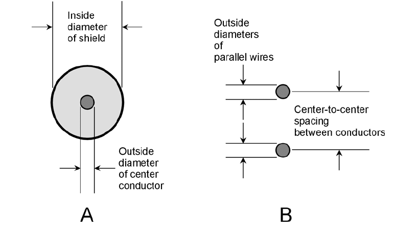
increases as the wire diameter gets smaller, and decreases as the wire diameter gets larger, all other
things being equal.
In a coaxial line, as the center conductor gets thicker, the Z
o
decreases if the shield stays the same
size. If the center conductor stays the same size and the shield increases in diameter, the Z
o
increases.
For either type of line, the Z
o
increases as the spacing between wires, or between the center con-
ductor and the shield, gets larger. The Z
o
decreases as the spacing is reduced. Solid dielectric mate-
rials such as polyethylene reduce the Z
o
of a transmission line, compared with air or a vacuum, when
placed between the conductors.
An Example of Z
o
in Practice
In rigorous terms, the ideal characteristic impedance for a transmission line is determined accord-
ing to the nature of the load with which the line works.
For a system having a purely resistive impedance of a certain number of ohms, the best line Z
o
value is that same number of ohms. If the load impedance is much different from the characteristic
impedance of the transmission line, excessive power is wasted in heating up the transmission line.
Imagine that you have a so-called 300-Ω frequency-modulation (FM) receiving antenna, such
as the folded-dipole type that you can mount indoors. Suppose that you want the best possible re-
ception. Of course, you should choose a good location for the antenna. You should make sure that
the transmission line between your radio and the antenna is as short as possible. But you should also
be sure that you purchase 300-Ω TV ribbon. It has a value of Z
o
that has been optimized for use
with antennas whose impedances are close to 300 + j0.
Characteristic Impedance 237
15-8 Edge-on views of coaxial transmission line (A) and parallel-wire line (B). In
either type of line, Z
o
depends on the conductor diameters and spacing, and
on the nature of the dielectric material between the conductors. See text for
discussion.
Impedance matching is the process of making sure that the impedance of a load (such as an an-
tenna) is purely resistive, with an ohmic value equal to the characteristic impedance of the transmis-
sion line connected to it. This concept will be discussed in more detail in the next chapter.
Conductance
In an ac circuit, electrical conductance works the same way as it does in a dc circuit. Conductance is
symbolized by the capital letter G. It was introduced in Chap. 2. The relationship between conduc-
tance and resistance is simple: G = 1/R. The standard unit of conductance is the siemens. The larger
the value of conductance, the smaller the resistance, and the more current will flow. Conversely, the
smaller the value of G, the greater the value of R, and the less current will flow.
Susceptance
Sometimes, you’ll come across the term susceptance in reference to ac circuits. Susceptance is sym-
bolized by the capital letter B. It is the reciprocal of reactance. Susceptance can be either capacitive
or inductive. These quantities are symbolized as B
C
and B
L
, respectively. Therefore we have these two
relations:
B
C
= 1/X
C
B
L
= 1/X
L
All values of B theoretically contain the j operator, just as do all values of X. But when it comes
to finding reciprocals of quantities containing j, things get tricky. The reciprocal of j is equal to its
negative! Expressed mathematically, we have these two facts:
1/j =−j
1/(−j ) = j
As a result of these properties of j, the sign reverses whenever you find a susceptance value in terms
of a reactance value. When expressed in terms of j, inductive susceptance is negative imaginary, and
capacitive susceptance is positive imaginary—just the opposite situation from inductive reactance
and capacitive reactance.
Suppose you have an inductive reactance of 2 Ω. This is expressed in imaginary terms as j2. To
find the inductive susceptance, you must find 1/( j2). Mathematically, this expression can be con-
verted to a real-number multiple of j in the following manner:
1/( j 2) = (1/j )(
1
⁄2)
= (1/j )0.5
=−j0.5
Now suppose you have a capacitive reactance of 10 Ω. This is expressed in imaginary terms as
−j10. To find the capacitive susceptance, you must find 1/(−j10). Here’s how this can be converted
to the straightforward product of j and a real number:
238 Impedance and Admittance
1/(−j10) = (1/−j )(
1
⁄10)
= (1/−j)0.1
= j 0.1
When you want to find an imaginary value of susceptance in terms of an imaginary value of reac-
tance, first take the reciprocal of the real-number part of the expression, and then multiply the re-
sult by −1.
Problem 15-5
Suppose you have a capacitor of 100 pF at a frequency of 3.00 MHz. What is B
C
?
First, find X
C
by the formula for capacitive reactance:
X
C
=−1/(6.28fC)
Note that 100 pF = 0.000100 µF. Therefore:
X
C
=−1/(6.28 × 3.00 × 0.000100)
=−1/0.001884 =−531 Ω
The imaginary value of X
C
is equal to −j531. The susceptance, B
C
, is equal to 1/X
C
. Thus, B
C
=
1/(−j531) = j0.00188, rounded to three significant figures.
The general formula for capacitive susceptance in siemens, in terms of frequency in hertz and
capacitance in farads, is:
B
C
= 6.28fC
This formula also works for frequencies in megahertz and capacitances in microfarads.
Problem 15-6
Suppose an inductor has L = 163 µH at a frequency of 887 kHz. What is B
L
?
Note that 887 kHz = 0.887 MHz. You can calculate X
L
from the formula for inductive
reactance:
X
L
= 6.28fL
= 6.28 × 0.887 × 163
= 908 Ω
The imaginary value of X
L
is equal to j908. The susceptance, B
L
= is equal to 1/X
L
. It follows that
B
L
=−1/j 908 =−j0.00110.
The general formula for inductive susceptance in siemens, in terms of frequency in hertz and
inductance in henrys, is:
B
L
=−1/(6.28fL)
This formula also works for frequencies in kilohertz and inductances in millihenrys, and for fre-
quencies in megahertz and inductances in microhenrys.
Susceptance 239
Admittance
Real-number conductance and imaginary-number susceptance combine to form complex admit-
tance, symbolized by the capital letter Y. This is a complete expression of the extent to which a cir-
cuit allows ac to flow.
As the absolute value of complex impedance gets larger, the absolute value of complex admit-
tance becomes smaller, in general. Huge impedances correspond to tiny admittances, and vice
versa.
Admittances are written in complex form just like impedances. But you need to keep track of
which quantity you’re talking about! This will be obvious if you use the symbol, such as Y = 3 − j0.5
or Y = 7 + j3. When you see Y instead of Z, you know that negative j factors (such as in the quan-
tity 3 − j 0.5) mean there is a net inductance in the circuit, and positive j factors (such as in the
quantity 7 + j3) mean there is net capacitance.
Admittance is the complex composite of conductance and susceptance. Thus, complex admit-
tance values always take the form Y = G + jB. When the j factor is negative, a complex admittance
may appear in the form Y = G − jB.
Do you remember how resistances combine with reactances in series to form complex imped-
ances? In Chaps. 13 and 14, you saw series RL and RC circuits. Did you wonder why parallel cir-
cuits were ignored in those discussions? The reason was the fact that admittance, not impedance, is
best for working with parallel ac circuits. Resistance and reactance combine in a messy fashion in
parallel circuits. But conductance (G ) and susceptance (B ) merely add together in parallel circuits,
yielding admittance (Y ). Parallel circuit analysis is covered in detail in the next chapter.
The GB Plane
Admittance can be depicted on a plane similar to the complex impedance (RX ) plane. Actually, it’s
a half plane, because there is ordinarily no such thing as negative conductance. (You can’t have a
component that conducts worse than not at all.) Conductance is plotted along the horizontal, or G,
axis on this coordinate half plane, and susceptance is plotted along the B axis. The GB plane is
shown in Fig. 15-9, with several points plotted.
It’s Inside Out
The GB plane looks superficially identical to the RX plane. But mathematically, the two could not
be more different! The GB plane is mathematically inside out with respect to the RX plane. The
center, or origin, of the GB plane represents the point at which there is no conduction for dc or for
ac. It is the zero-admittance point, rather than the zero-impedance point. In the RX plane, the ori-
gin represents a perfect short circuit, but in the GB plane, the origin corresponds to a perfect open
circuit.
As you move out toward the right (east) along the G, or conductance, axis of the GB plane, the
conductance improves, and the current gets greater. When you move upward (north) along the jB
axis from the origin, you have ever-increasing positive (capacitive) susceptance. When you go
down (south) along the jB axis from the origin, you encounter increasingly negative (inductive)
susceptance.
240 Impedance and Admittance
