George W. Stimson introduction to Airborne Radar (Se)
Подождите немного. Документ загружается.

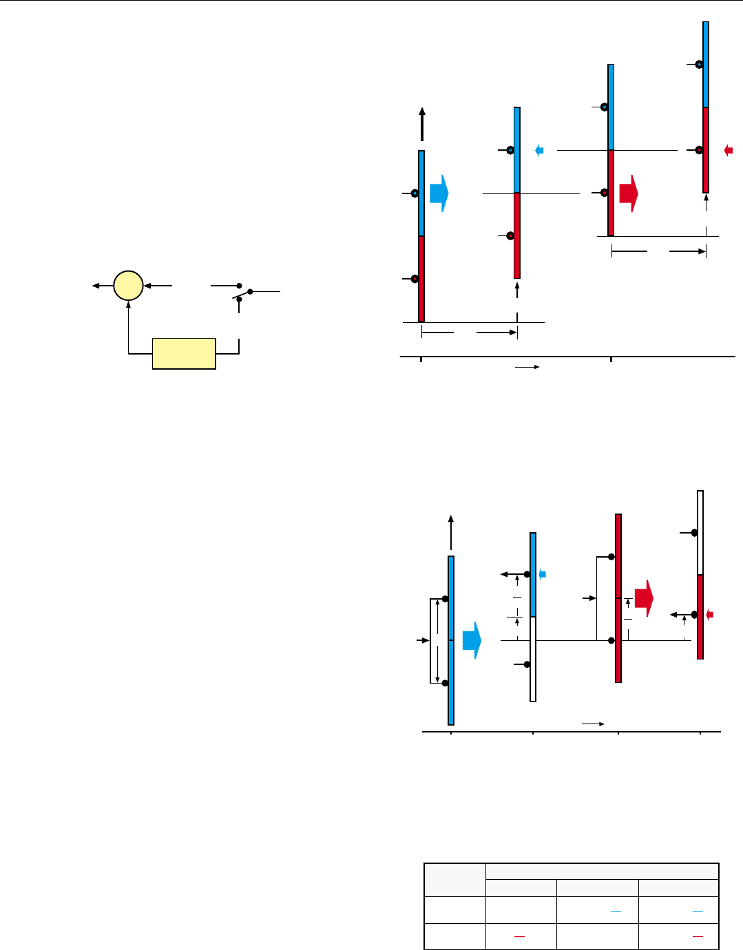
But if V is constant, this advance will be the same for
both pulses. Therefore, the round-trip distance traveled by
the pulses to any one point on the ground will be the same,
making the phases of the returns the same (Fig. 3).
So, for each resolvable range interval the radar returns
received from the ground may be canceled simply by pass-
ing the digitized video outputs of the radar receiver through
a single-pulse-delay clutter canceler. As illustrated below, it
delays the return of pulse (n) by the interpulse period, T,
and subtracts it from the return of pulse (n + 1).
CHAPTER 24 Separating Ground-Moving Targets from Clutter
319
3. Returns of each pulse are received by the same segment that
transmitted the pulse. Consequently, round-trip distances trav-
eled by both pulses n and (n + 1) will be equal.
Successive returns from a moving target, however, will
differ in phase as a result of the radial component of the tar-
get’s velocity
. Consequently, they will not cancel but will pro-
duce a useful output.
Effective as this technique is, it has four limitations:
1. The PRF is tied to the aircraft’s velocity
2. Very tight constraints are placed on aircraft and
antenna motion
3. The phase and amplitude characteristics of the two
antenna segments and of the receive channels for
both segments must be precisely matched
4. Only half of the aperture is used at any one time
The fourth limitation may be partially removed by adjust-
ing the velocity and PRF so that during the interpulse period
the phase centers advance by only half the distance between
them (Fig. 4), the entire aperture may be used for transmis-
sion. But still only half the aperture may be used for recep-
tion. Returns of pulse (n) must be received by the forward
segment; returns of pulse (n + 1), by the aft segment.
Although both pulses are not transmitted from the same
point in space and returns from the same ranges are not
received at the same points in space, the result is the same
as if they were. For as indicated in the table at right, the
phase centers’ total displacement for transmission and
reception is the same for both pulses. Therefore, the round-
trip distance traveled to any one point on the ground is the
same for both pulses—just as when the pulses are alternate-
ly transmitted by the fore and aft antenna segments.
V
Return
(n)
Return
(n + 1)
t
R
= round trip transit time to
range, R, of target from
which return is received
Pulse
(n)
Pulse
(n + 1)
COMPLETE DPCA CYCLE
t
R
0
T
Time
V t
R
t
R
V t
R
Σ
+
–
Delay = T
(1/PRF)
Returns
from
Range R
Summer
To Doppler
Filtering
Pulse
(n + 1)
Pulse
(n)
CLUTTER CANCELER
4.
To transmit with full aperture, velocity, V, and PRF are adjusted
so the radar travels only half the distance between phase cen-
ters during interpulse period. Returns of pulse
n
are received
by the forward antenna segment; returns of pulse
(n + 1)
, by
the aft segme
nt. So the round trip distance traveled by both
pulses is the same.
V
t
t + T
Return (n)
t = t
R
(t + T) + t
R
Time
Pulse
(n)
V t
R
d
MODIFIED DCPA
Pulse
(n+1)
d
2
t
R
= round-trip transit
time to range, R,
of target from
which returns
are received.
Return (n + 1)
V t
R
d
2
Pulse
Displacement of Phase Centers
Transmit Receive Total
(n)
(n + 1)
0V t
R
+ V t
R
+
V t
R
V t
R
+
d
2
d
2
d
2
d
2
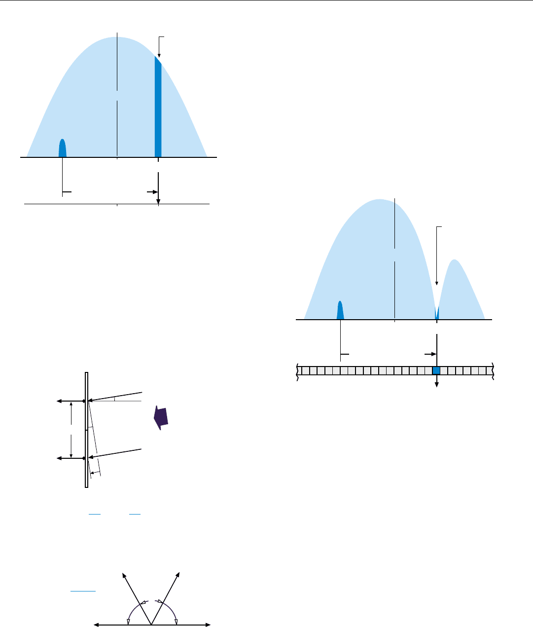
5. Relationship between return received from a slowly moving
target on the ground and mainlobe clutter. Because of tar-
get‘s radial component of velocity, clutter having the same
doppler frequency as the target, f
n
, is received from a differ-
ent angle off the boresight line.
6. Placing a notch in the antenna receive pattern at angle, θ
n
,
from which the radar receives mainlobe clutter having the
same doppler frequency, f
n
, as target, n, prevents clutter from
interfering with the target‘s detection. Doppler filtering isolates
the target return from other clutter.
PART V The Problem of Ground Clutter
320
Notching Technique
Notching has the advantage over Classical DPCA of not
requiring that the PRF be tied to aircraft velocity and of
relaxing the constraints on aircraft and antenna motion.
Mainlobe clutter is rejected without rejecting target returns
by taking advantage of the doppler shift due to the radial
component of a target’s velocity, small as it may be. Because
of this shift, clutter having the same doppler frequency as
target n comes from a slightly different angle,
θ
n
, off the
boresight line (Fig. 5). Therefore, by placing a notch in the
antenna receive pattern at
θ
n
, the clutter can be rejected
without rejecting the return from target n (Fig. 6).
Return From
Target n
Clutter having
same doppler
frequency as
target n.
Boresight Line
MLC
Doppler Filter Bank
Target
Return
Angle Off Boresight
(+)(–)
0
Shift due to target’s radial
component of velocity.
n
θ
Return From
Target n
Clutter having
same doppler
frequency as
target n.
Boresight Line
MLC
Angle Off Boresight
(+)
(–) 0
f
n
Doppler Frequency
(+)(–) 0
Shift due to target’s radial
component of velocity.
n
θ
Moreover, the return from target n is isolated from clutter
received from other directions—and therefore having other
doppler frequencies—by doppler filtering.
Because a target’s angular position and radial component
of velocity generally are not known in advance, and because
returns from targets in different directions may be received
simultaneously, a separate notch must be formed for each of
the N resolvable doppler frequencies. To avoid rejecting tar-
get returns along with the clutter, notching must be per-
formed after, not before, doppler filtering.
The notches are produced with an interferometric tech-
nique similar to that used in phase-comparison monopulse
angle tracking (see panel, left). As with Classical DPCA, a
two-segment electronically steered antenna is typically
used. So that very small differences in doppler frequency
may be resolved, dwell times are increased to allow prede-
tection integrated over long periods, t
int
. So that the notch-
HOW A NOTCH IS MADE
In a Two-Segment Antenna’s Receive Pattern
At an Angle θ
n
Off the Boresight Line
1. Calculate the difference in distance, ∆
d
, traveled to the
two phase centers, A and B, by returns from a distant
point at the angle, θ
n
, off the boresight line.
2. Convert ∆
d
to phase, φ.
3. Subtract
φ from π radians (180 °). Divide by 2. Result is
the phase rotation, ∆
φ, which—when made in opposite
directions to antenna outputs A and B—will increase the
phase difference,
φ, between returns received from θ
n
to
180°.
5. Sum the phase-rotated outputs, A' and B'. The returns
received from θ
n
will then cancel, producing the equiva-
lent of a notch in the antenna receive pattern at angle θ
n
.
6. To produce a notch on the opposite side of the boresight
line, reverse the directions of the two phase rotations.
φ = ∆
d
= W sin θ
n
2 π
λ
2 π
λ
B
A
W
Radar return
from angle q
n
∆
d
=
W sin θ
n
∆φ =
π – φ
2
+ ∆
φ
A
A'
B
B'
φ
– ∆
φ
θ
θ
θ
θ
θ
n
θ
n
θ
θ
θ
θ
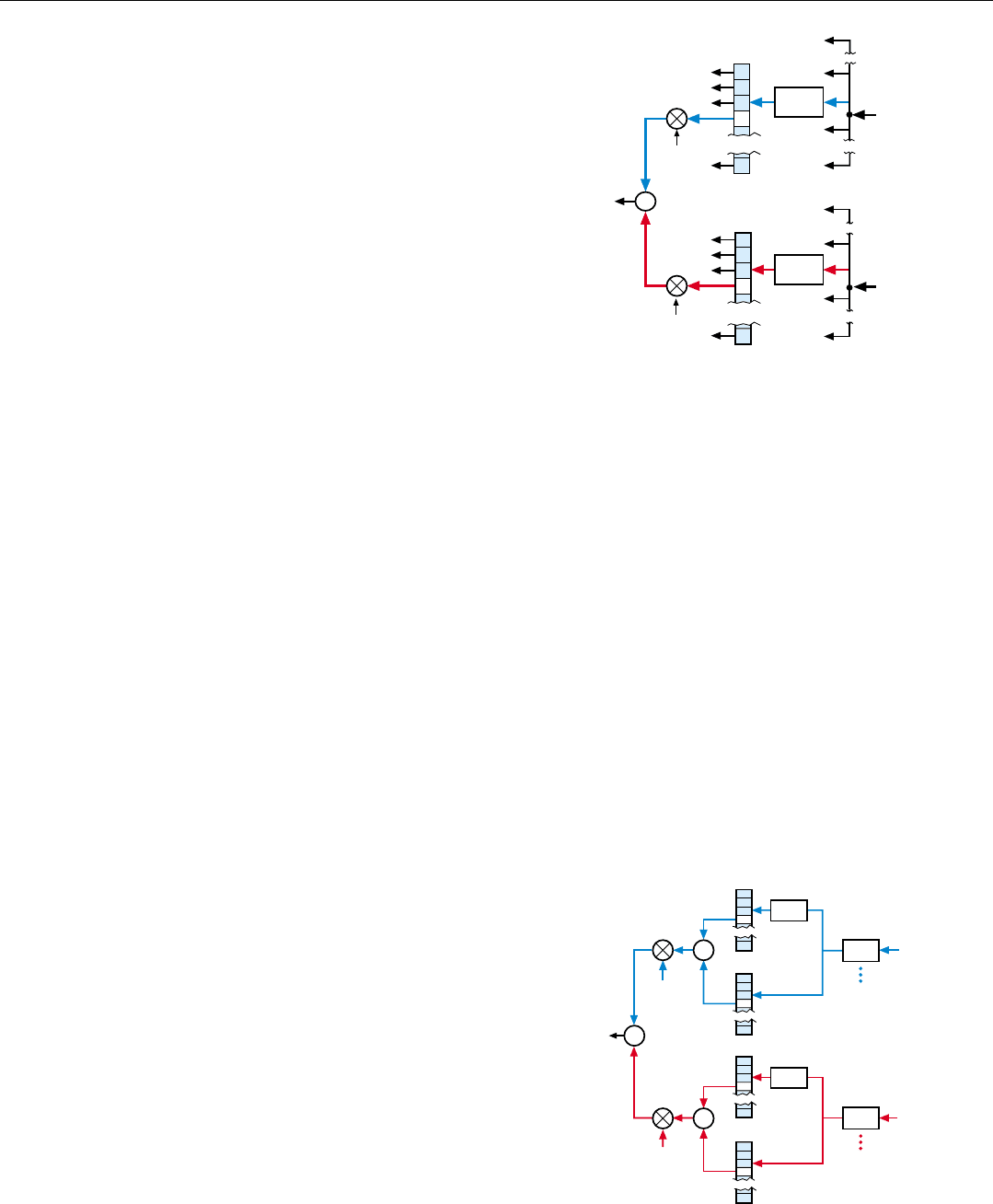
ing can be done in the signal processor, a separate receive
and signal processing channel is generally provided for each
antenna segment.
Implementation of the notching process is illustrated in
abbreviated form in Fig. 7. For every range bin in both
Channel A and Channel B, a separate doppler filter bank is
formed. The outputs of each pair of filters, n, passing
returns of the same frequency, f
n
, from the same range, m,
are then rotated in opposite directions through the angle,
∆φ
n
. This rotation causes the returns received by the two
antenna segments from the ground at an angle θn off the
boresight line to be 180° out of phase.
The phase-rotated returns are summed, with the result
that the ground returns from
θ
n
cancel, while returns from
targets at any other angle off the boresight line whose
doppler frequency is f
n
do not.
For radars in which monopulse sum and difference sig-
nals for angle tracking are produced ahead of the receiver
(i.e., at microwave frequencies), notching is performed sim-
ilarly with the outputs of the sum and difference channels.
In that case, though, rather than being phase rotated and
summed, the outputs of corresponding doppler filters, f
n
,
are weighted and summed to shift the null of the difference
output to the angle
θ
n
off boresight.
In view of the fact that a good many targets on the
ground will have high enough radial velocities to fall in the
clutter-free portion of the doppler spectrum, notching is
generally time shared with conventional moving-target-
indication processing.
Combined Notching and Classical DPCA
Generally, notching provides very good mainlobe clutter
cancellation. But, under some conditions—such as when
frame-time requirements limit dwell times hence achievable
doppler resolution—clutter rejection performance can be
substantially improved by combining notching and
Classical DPCA. This improvement may at any time be
traded to various degrees for an easing of Classical DPCA’s
strict constraints on aircraft and antenna motion and/or for
uncoupling PRF from aircraft velocity.
Implementation differs from that just described primarily
in that for each range bin, two doppler filter banks are
formed from the outputs of each receive channel, and the
inputs to one of these banks are delayed by the interpulse
period, T (Fig. 8).
Although further improvements in clutter rejection per-
formance can be expected, it should be borne in mind that,
since the cancellation techniques rely on clutter scatterers
being stationary, cancellation ultimately will be limited by
the “internal motion” of the clutter.
CHAPTER 24 Separating Ground-Moving Targets from Clutter
321
8. Combination of classical DPCA and notching. Technique can
be used to ease constraints DPCA places on aircraft and
antenna motion or improve clutter rejection performance of
notching in applications that limit dwell time.
9. Implementation of notching technique. Video outputs of
receive channels A and B are collected in range bins. For
each range bin, m, a doppler filter bank is formed. Output of
each filter, n, is rotated in phase in Channel A by +∆φ
n
and in
Channel B by –∆φ
n
. Rotated outputs are then summed, creat-
ing the equivalent of a notch in the antenna receive pattern at
θ
n
, while passing returns from targets at other angles whose
doppler frequency is f
n
.
Range
Bins
Filter
Banks
Phase
Rotation
+ ∆φ
n
− ∆φ
n
Σ
Output of
Receive
Channel
A
Output of
Receive
Channel
B
Bin m
Moving
Target
Returns
Range, m;
Doppler
Frequency, f
n
Bin m
n
n
Σ
Moving
Target
Returns
Filter
Banks
Phase
Rotation
+ ∆φ
n
-
+
1/PRF
From
Receive
Channel A
Bin m
Range
Bins
Delay
n
Σ
+ ∆φ
n
-
+
1/PRF
From
Receive
Channel B
Bin m
n
n
n
Σ
PART V The Problem of Ground Clutter
322
Precise Angle Measurement
While the DPCA and notching techniques enable a target
to be detected which would otherwise be hopelessly embed-
ded in mainlobe clutter, they don’t tell at what angle within
the antenna beam the target is located. For although the
direction of the interfering clutter can be determined from
the frequency of the doppler filter that passes the target
return, without knowing the target’s radial velocity, hence its
doppler frequency, it is impossible to tell directly how far
removed from that angle the target actually is.
In conventional operation of a two-segment antenna and a
two-channel receiving system, a target’s precise direction may
be obtained by comparing the phases, or amplitudes, of the
outputs the target produces from the two channels. But the
slow-moving-target detection techniques fully utilize the out-
puts of both channels for clutter rejection and target detection.
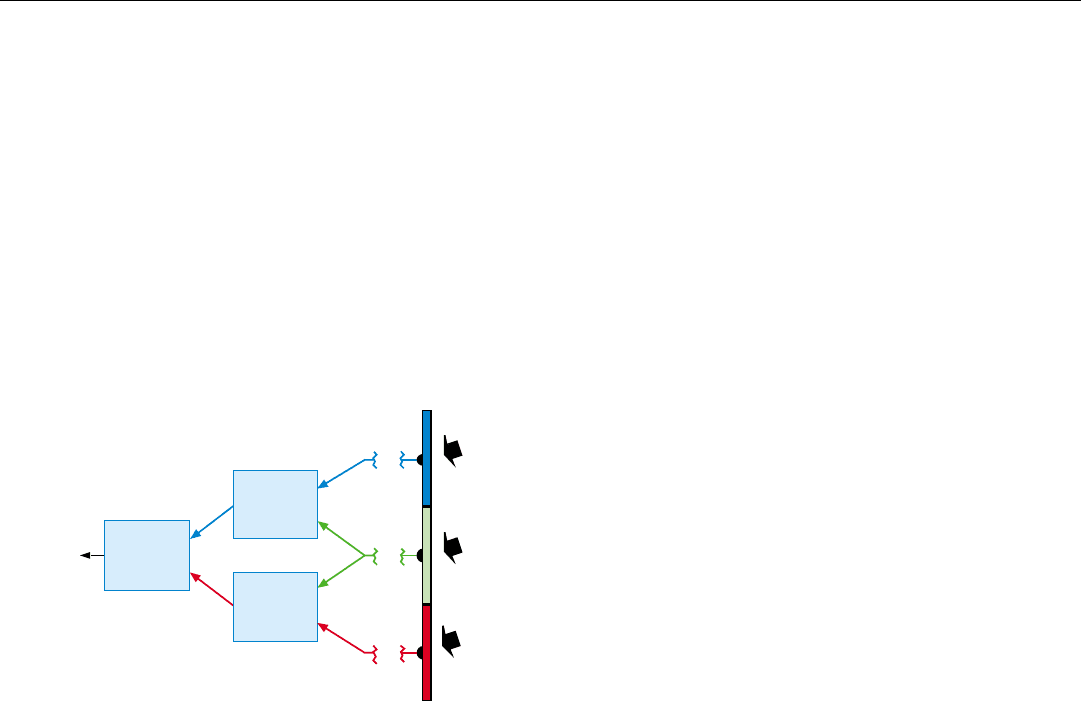
Accordingly, where precise angle measurement is required,
a three-segment antenna and three receive channels are gener-
ally provided. As illustrated in Fig. 9, the outputs of receive
channels A and B are used to provide clutter rejection and tar-
get detection for an effective phase center half way between
the phase centers of antenna segments A and B. The outputs
of channels B and C are similarly used to provide clutter
rejection and target detection for an equivalent phase center
half way between those of antenna segments B and C. The tar-
get’s precise direction is then estimated on the basis of the dis-
tance between the two effective phase centers and the differ-
ence in phase of the two output signals.
Summary
Targets whose true doppler frequencies fall in mainlobe
clutter are commonly separated from the clutter with either
Classical DPCA or notching, both of which employ a two-
segment side-looking antenna.
For DPCA, aircraft velocity and PRF are adjusted so the
radar advances the distance between the segments’ phase cen-
ters during the interpulse period. By transmitting and receiv-
ing alternate pulses with fore and aft segments, both pulses
travel the same round-trip distance to any one point on the
ground; so MLC can be eliminated by a clutter canceller.
For notching, radar returns are sorted with a doppler filter
bank, and a notch is placed in the antenna receive pattern for
each filter. Because of the doppler shift due to a target’s veloc-
ity, MLC having the same doppler frequency as the target will
come from a different direction than target return. So, the
clutter is “notched out” without rejecting target returns.
By combining DPCA with notching, greater flexibility
may be obtained than with either technique alone.
To pinpoint a detected target’s position within the anten-
na’s mainlobe, a third antenna segment must be provided.
9. Approach to precise angle measurement. Since returns
received by two antenna segments are required for clutter
elimination and target detection, a third segment must be pro-
vided to determine target‘s angle,
θ
, within the radar‘s beam.
Channel
A
Channel
B
Angle
Measure-
ment
Clutter
Elimination
&
Detection
Channel
C
Clutter
Elimination
&
Detection
Angular
Position
θ
325
The Crucial
Choice of PRF
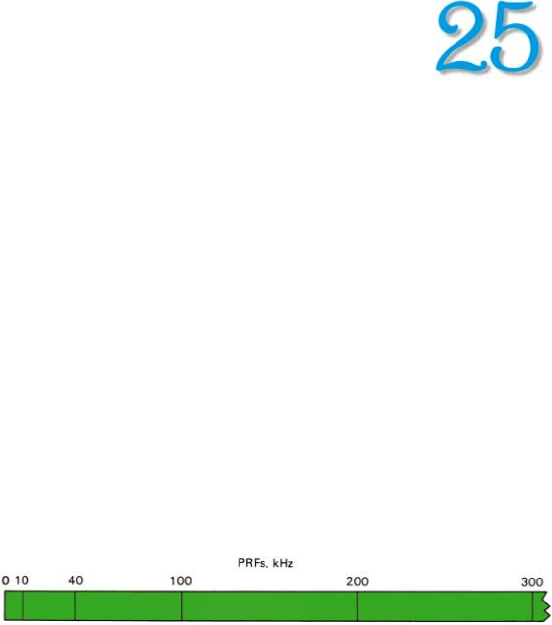
1. PRFs used by airborne radars range all the way from a few hundred hertz to several hundred kilohertz.
F
ew parameters of a pulsed radar are more impor-
tant than the PRF. This is particularly true of
doppler radars. Other conditions remaining the
same, the PRF determines to what extent the
observed ranges and doppler frequencies will be ambigu-
ous. That, in turn, determines the ability of the radar not
only to measure range and closing rate directly, but to
reject ground clutter. In situations where substantial
amounts of clutter are encountered, the ability to reject
clutter crucially affects the radar’s detection capability.
In this chapter we will survey the wide range of pulse
repetition frequencies employed by airborne radars and
see in what regions significant range and doppler ambigui-
ties may occur. We will then take up the three basic cate-
gories of pulsed operation — low, medium, and high
PRF— and learn what their relative merits are.
Primary Consideration: Ambiguities
The pulse repetition frequencies used by airborne
radars vary from a few hundred hertz to several hundred
kilohertz (Fig. 1). Exactly where, within this broad spec-
trum, a radar will perform best under a given set of condi-
tions depends upon a number of considerations. The most
important of these are range and doppler ambiguities.
PART VI Air-to-Air Operation
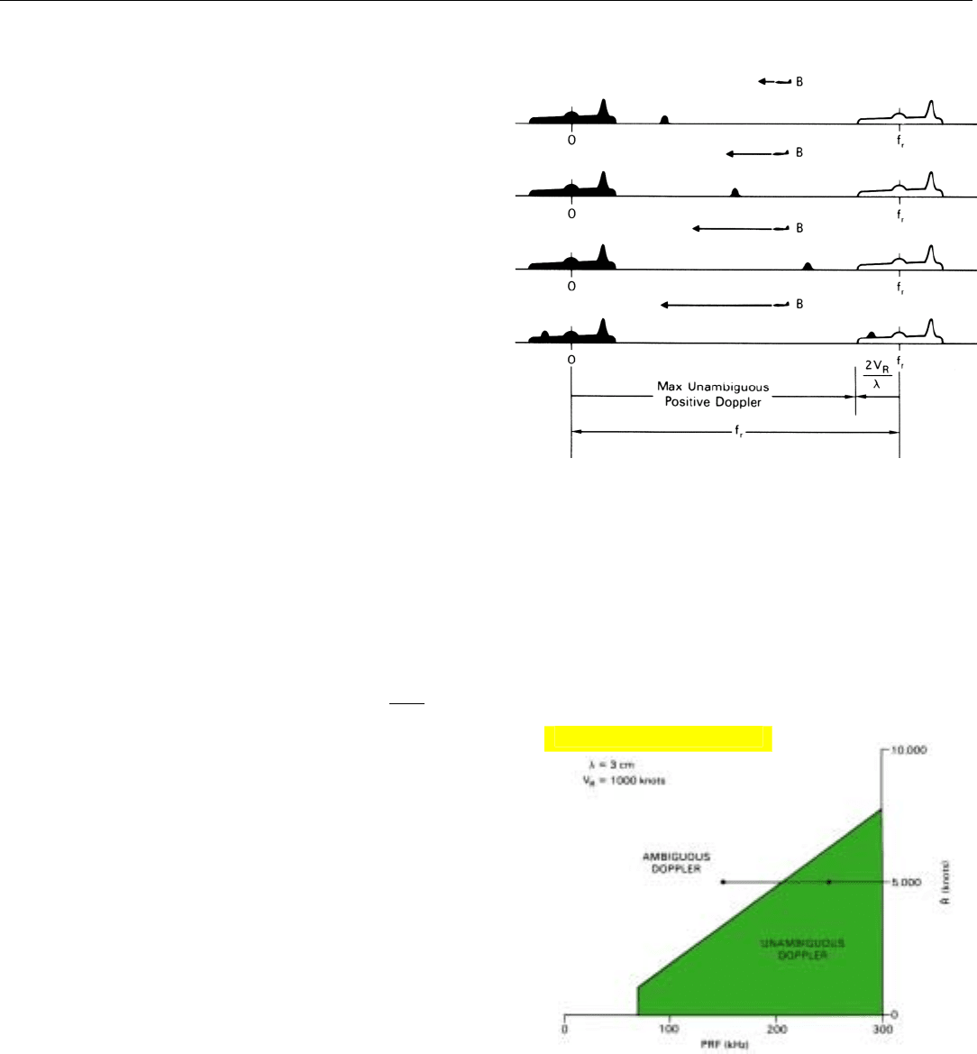
4. Maximum opening rate is usually that of ground from which side-
lobe clutter is received behind radar. Maximum closing rate is
that of fastest approaching target.
326
Range Ambiguities. As we have seen, for range to be
unambiguous, the echoes from the most distant detectible
targets must be first-time-around echoes. In other words, all
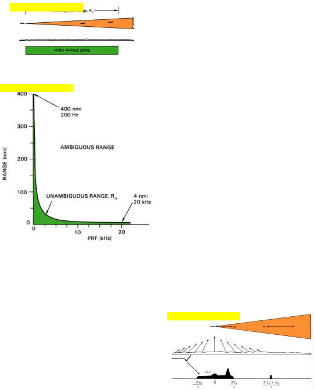
sources of detectable return must lie in the first range zone:
their ranges must be less than the unambiguous range, R
u
(Fig. 2). Because targets of large radar cross section, as well
as return from the ground, may be detected at exceptionally
long ranges, range is almost always ambiguous.
However, if the PRF is sufficiently low so that the maxi-
mum required operating range falls within the first range
zone, ambiguities can be eliminated by rejecting any return
received from beyond R
u
. (Techniques for rejecting it are
described in Chap. 12.) Under this condition, the first
range zone is a region of unambiguous range.
The first range zone extends to a range very nearly equal
to 80 nautical miles divided by the PRF in kilohertz. In
Fig. 3, this range is plotted versus PRF. The area under the
curve encompasses every combination of PRF and true
range for which range is unambiguous. The area above the
curve encompasses every combination for which range is
invariably ambiguous.
Notice how rapidly the curve plunges as the PRF is
increased. From a range of 400 miles at a PRF of 200 hertz,
it drops to 10 miles at a PRF of 8 kilohertz and to only 4
miles at a PRF of 20 kilohertz.
Doppler Ambiguities. Like range, doppler frequency is
inherently ambiguous. Whether the ambiguities are signifi-
cant, however, depends not only upon the PRF but upon
the wavelength and the spread between the maximum
opening and closing rates likely to be encountered. The
maximum closing rate is usually the rate of the most rapidly
approaching target. The maximum opening rate may be
either that of the most rapidly opening target or that of the
ground from which sidelobe clutter is received behind the
radar (Fig. 4). In fighter applications, it is generally the lat-
ter. This rate is very nearly equal to the maximum velocity
of the aircraft carrying the radar.
2. Assuming all return from beyond first range zone is rejected,
this zone is a region of unambiguous range.
3. Area under curve encompasses every combination of range and
PRF for which a target‘s observed range will be unambiguous,
assuming all return from beyond first range zone is either
negligible or rejected.
Click for high-quality image
Click for high-quality image
Click for high-quality image
CHAPTER 25 The Crucial Choice of PRF
The relationship between the PRF and the doppler fre-
quency at which ambiguities arise in a clutter environment
is illustrated in Fig. 5.
It shows the doppler profile for the flight situation pre-
sented in Chap. 23 and includes both the true profile (cen-
tral-line frequencies) and the next-higher-frequency repeti-
tion of it (first upper sideband frequencies). Corresponding
points in the two profiles are, of course, separated by the
pulse repetition frequency. A high closing rate target (B)
appears in the clear region above the highest true clutter
frequency. If this target’s closing rate were progressively
increased, the target would move up the doppler frequency
scale and into the repetition of the sidelobe clutter spec-
trum. On the basis of doppler frequency, alone, the radar
would have no way of separating the target echoes from the
sidelobe clutter, even though their true doppler frequencies
are quite different.
From the standpoint of clutter rejection, therefore, the
highest unambiguous doppler frequency a target can
have—i.e., the highest frequency at which the target will
not have to compete with clutter whose true doppler fre-
quency is different from the target’s—equals the pulse repe-
tition frequency minus the maximum sidelobe clutter fre-
quency. The latter frequency, as we just noted, corresponds
to the radar’s velocity.
Maximum unambiguous doppler = PRF –
(
2V
R
)
λ
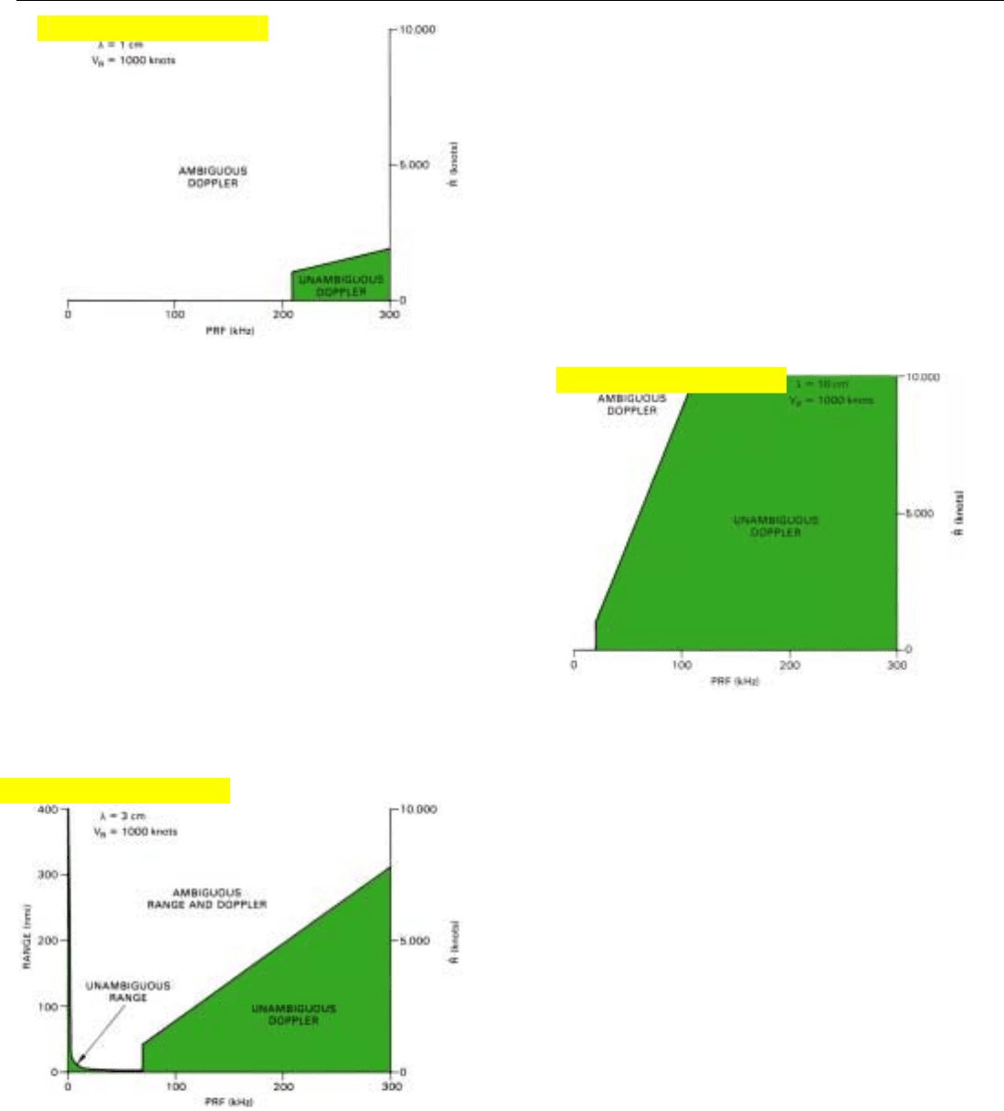
The maximum closing rate for which the doppler fre-
quency will be unambiguous in a clutter environment is
plotted versus PRF in Fig. 6. A wavelength of 3 centimeters
and a radar velocity of 1000 knots are assumed. The plot
decreases linearly from a closing rate of about 8000 knots at
a PRF of 300 kilohertz to a closing rate of 1000 knots
(radar’s ground speed) at a PRF of 70 kilohertz. (It is termi-
nated at this point since at lower PRFs the maximum posi-
tive and negative sidelobe clutter frequencies overlap.)
The area beneath the curve encompasses every combina-
tion of PRF and closing rate for which the observed doppler
frequencies are unambiguous. Conversely, the area above
the curve encompasses every combination for which the
doppler frequencies are ambiguous. For example, at a PRF
of 250 kilohertz, and a closing rate of 5000 knots the
doppler frequency is unambiguous, whereas at a PRF of
150 kilohertz and the same closing rate, the doppler fre-
quency is ambiguous.
If the radar-carrying aircraft’s ground speed is greater
than 1000 knots, the area beneath the curve will be corre-
spondingly reduced, and vice versa.
327
5. True doppler profile and next higher repetition of it. As com-
ponent of target velocity along line of sight to radar increas-
es, target moves through doppler clear region and ultimately
enters repetition of negative frequency sidelobe clutter.
6. Combinations of PRF and closing rate, R
˙
, for which observed
doppler frequencies are unambiguous.
Click for high-quality image
PART VI Air-to-Air Operation
8. Dramatic
increase
in region of unambiguous doppler frequency
resulting from increase in wavelength to 10 centimeters.
9. When region of unambiguous range is plotted to same scale
as PRF, it becomes apparent that choice of PRF is, at best, a
compromise.
328
Since doppler frequency is inversely related to wave-
length, the shorter the wavelength, the more limited the
region of unambiguous doppler frequencies will be. To
illustrate the profound effect of wavelength on doppler
ambiguities, Fig. 7 plots the maximum closing rate at
which the doppler frequency will be unambiguous for a
one centimeter wavelength. Not only is the area under the
curve comparatively small, but even at a PRF of 300 kilo-
hertz, the maximum closing rate at which the PRF is unam-
biguous is less than 2000 knots.
Yet, at a wavelength of 10 centimeters the area under the
curve extends from 1000 knots at 21 kilohertz to about
27,000 knots (off the scale) at 300 kilohertz (Fig. 8).
7. Dramatic reduction in region of unambiguous doppler fre-
quencies resulting from decrease in wavelength λ from 3 to 1
centimeter.
Putting the Plots in Perspective. The regions of unam-
biguous range and unambiguous doppler frequency (for λ
= 3 cm and V
R
= 1000 knots) are shown together in Fig. 9.
Drawn to the scale of this diagram, the region of unambigu-
ous range (first range zone) is quite narrow. To the right of
it is the comparatively broad region of unambiguous
doppler frequencies. In between is a region of considerable
extent within which both range and doppler frequency are
ambiguous.
Clearly, the choice of PRF is a compromise. If the PRF is
increased beyond a relatively small value, the observed
ranges will be ambiguous. And unless the PRF is raised to a
much higher value than that, the observed doppler fre-
quencies will be ambiguous.
While both range and doppler ambiguities make clutter
rejection difficult, as we shall see their effects on a radar’s
operation are fortuitously quite different. It turns out that
by designing a radar to operate over a wide range of PRFs
and by judiciously selecting the PRF to suit the operational
requirements at the time, the difficulties can be almost
completely obviated.
Click for high-quality image
Click for high-quality image
Click for high-quality image
CHAPTER 25 The Crucial Choice of PRF
329
The Three Basic Categories of PRF
Because of the tremendous impact the choice of PRF has
on performance, it is customary to classify airborne radars
in terms of their PRFs. Recognizing that the regions of
unambiguous range and unambiguous doppler frequency
are very nearly mutually exclusive, three basic categories of
PRF have been established: “low,” “medium,” and “high.”
These are defined in terms not of the numerical value of
the PRF per se, but of whether the PRF is such that the
observed ranges and/or doppler frequencies are ambiguous.
While exact definitions vary, all are similar. The following is
a widely used, consistent set of definitions.
• A low PRF is one for which the maximum range the
radar is designed to handle lies in the first range zone.
In the absence of return from beyond this zone, range
is unambiguous.
• A high PRF is one for which the observed doppler fre-
quencies of all significant targets are unambiguous.
• A medium PRF is one for which neither of these con-
ditions is satisfied. Both range and doppler frequency
are ambiguous.
Which category a particular PRF falls in depends to a
considerable extent upon the operating conditions. A PRF
of 4 kilohertz—first range zone extending to 20 nautical
miles—would be “low” if the maximum target range were
less than 20 miles (Fig. 10). Yet the same PRF, 4 kilohertz,
would be “medium” if the maximum range were greater
than 20 miles and the spread between maximum positive
and negative doppler frequencies exceeded 4 kilohertz.
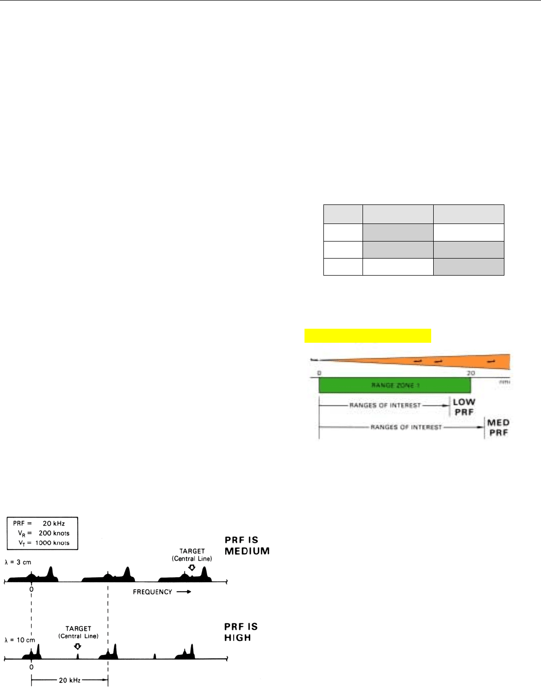
Similarly, a PRF of 20 kilohertz might be “medium” for a
3-centimeter radar (X-band), yet “high” for a 10-centimeter
radar (S-band) if, say, the radar’s velocity were 200 knots
and the velocity of the fastest target, 1000 knots—maxi-
mum closing rate 1200 knots (Fig. 11).
10. A PRF of 4 kilohertz would be LOW if maximum range of
interest was less than 20 miles; yet MEDIUM if maximum
range of interest was greater than 20 miles.
11. A PRF of 20 kilohertz might be medium at a wavelength of 3 cen-
timeters, yet high at a wavelength of 10 centimeters.
CATEGORIES OF PRF
PRF RANGE DOPPLER
HIGH Ambiguous Unambiguous
MED Ambiguous Ambiguous
LOW Unambiguous Ambiguous
Click for high-quality image
PART VI Air-to-Air Operation
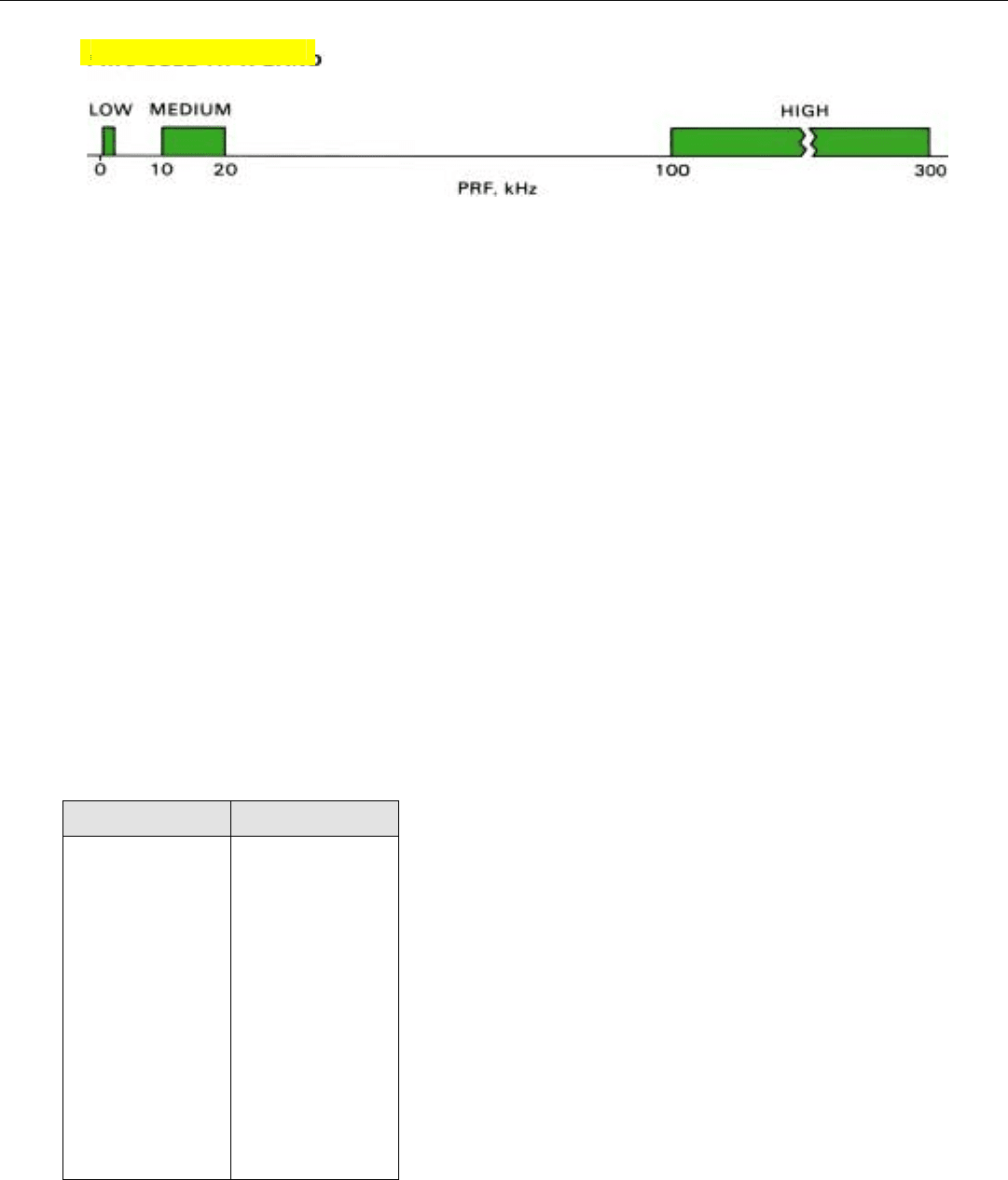
12. In practice, not all of the PRFs within each category are used. Reason will be made clear in subsequent chapters.
330
In practice, not all of the possible PRFs within each cate-
gory are used for any one radar band (Fig. 12, above). At X-
band, for example, PRFs in the low category typically run
from 250 to 4000 hertz; PRFs in the medium category are
on the order of 10 to 20 kilohertz; PRFs in the high catego-
ry may range anywhere from 100 to 300 kilohertz.
One should not get the idea that the classifications are
technicalities of little practical importance. To the contrary,
in the everyday world of radar development and applica-
tion, they have proved to be immensely useful—especially
regarding fighter and airborne early warning radars. As we
shall see in subsequent chapters, whereas changing the PRF
within any one category does not alter the radar’s design in
any fundamental way, changing the PRF from one category
to another radically affects both the radar’s signal processing
requirements and its performance.
In fighter radars, the three categories of PRF complement
one another nicely from the standpoint of performance.
Low PRF Operation. Because range is unambiguous at
low PRFs, this mode of operation has two important advan-
tages. First, range may be measured directly by simple pre-
cise pulse delay ranging. Second, as will be explained in the
next chapter, virtually all sidelobe return can be rejected
through range resolution.
1
However, unless the mainlobe clutter is separated in
range from the targets the radar encounters, it can be reject-
ed only on the basis of differences in doppler frequency. And
because of the overlapping of successive repetitions of the
doppler spectrum at low PRFs, the clutter cannot be rejected
without also rejecting the returns from a considerable por-
tion of the spectrum in which targets may appear. If the
wavelength is long enough, the ground speed low enough
(f
d
∝V
R
/λ), and the antenna large enough (θ
3dB
∝λ/d) the
mainlobe clutter spectrum will be sufficiently
narrow that
the possible loss of target return is quite tolerable.
But for the conditions under which most fighter radars
must operate—short wavelength, small antenna, and
potentially high ground speed—if the PRF is low enough to
extend the first range zone out to reasonably long ranges—
30 or 40 miles—the unambiguous doppler spectrum is col-
1. Except for return from point
targets of exceptionally large
radar cross section.
LOW PRFs
ADVANTAGES LIMITATIONS
1. Good for air-to-air look- 1. Poor for air-to-air look-
up and ground down—much target
mapping. return may be rejected
along with mainlobe
clutter.
2. Good for precise range 2. Ground moving targets
measurement and fine can be a problem.
range resolution.
3. Simple pulse delay 3. Doppler ambiguities
ranging possible. generally too severe
to be resolved.
4. Normal sidelobe return
can be rejected
through range
resolution.
Click for high-quality image
