Elmasri R., Navathe S.B. Fundamentals of Database Systems
Подождите немного. Документ загружается.

222 Chapter 7 Data Modeling Using the Entity-Relationship (ER) Model
constraint is specified by a single line for partial participation and by double lines
for total participation (existence dependency).
In Figure 7.2 we show the role names for the
SUPERVISION relationship type
because the same
EMPLOYEE entity type plays two distinct roles in that relationship.
Notice that the cardinality ratio is 1:N from supervisor to supervisee because each
employee in the role of supervisee has at most one direct supervisor, whereas an
employee in the role of supervisor can supervise zero or more employees.
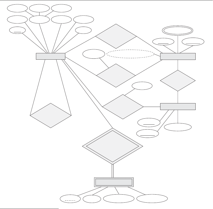
Figure 7.14 summarizes the conventions for ER diagrams. It is important to note
that there are many other alternative diagrammatic notations (see Section 7.7.4 and
Appendix A).
7.7.2 Proper Naming of Schema Constructs
When designing a database schema, the choice of names for entity types, attributes,
relationship types, and (particularly) roles is not always straightforward. One
should choose names that convey, as much as possible, the meanings attached to the
different constructs in the schema. We choose to use singular names for entity types,
rather than plural ones, because the entity type name applies to each individual
entity belonging to that entity type. In our ER diagrams, we will use the convention
that entity type and relationship type names are uppercase letters, attribute names
have their initial letter capitalized, and role names are lowercase letters. We have
used this convention in Figure 7.2.
As a general practice, given a narrative description of the database requirements, the
nouns appearing in the narrative tend to give rise to entity type names, and the verbs
tend to indicate names of relationship types. Attribute names generally arise from
additional nouns that describe the nouns corresponding to entity types.
Another naming consideration involves choosing binary relationship names to
make the ER diagram of the schema readable from left to right and from top to bot-
tom. We have generally followed this guideline in Figure 7.2. To explain this naming
convention further, we have one exception to the convention in Figure 7.2—the
DEPENDENTS_OF relationship type, which reads from bottom to top. When we
describe this relationship, we can say that the
DEPENDENT entities (bottom entity
type) are
DEPENDENTS_OF (relationship name) an EMPLOYEE (top entity type).
To change this to read from top to bottom, we could rename the relationship type to
HAS_DEPENDENTS, which would then read as follows: An EMPLOYEE entity (top
entity type)
HAS_DEPENDENTS (relationship name) of type DEPENDENT (bottom
entity type). Notice that this issue arises because each binary relationship can be
described starting from either of the two participating entity types, as discussed in
the beginning of Section 7.4.
7.7.3 Design Choices for ER Conceptual Design
It is occasionally difficult to decide whether a particular concept in the miniworld
should be modeled as an entity type, an attribute, or a relationship type. In this

7.7 ER Diagrams, Naming Conventions, and Design Issues 223
MeaningSymbol
Entity
Weak Entity
Indentifying Relationship
Relationship
Composite Attribute
. . .
Key Attribute
Attribute
Derived Attribute
Multivalued Attribute
Total Participation of E
2
in R
RE
1
E
2
Cardinality Ratio 1: N for E
1
:E
2
in R
R
E
1
E
2
N1
Structural Constraint (min, max)
on Participation of E in R
R
E
(min, max)
Figure 7.14
Summary of the notation
for ER diagrams.
224 Chapter 7 Data Modeling Using the Entity-Relationship (ER) Model
section, we give some brief guidelines as to which construct should be chosen in
particular situations.
In general, the schema design process should be considered an iterative refinement
process, where an initial design is created and then iteratively refined until the most
suitable design is reached. Some of the refinements that are often used include the
following:
■
A concept may be first modeled as an attribute and then refined into a rela-
tionship because it is determined that the attribute is a reference to another
entity type. It is often the case that a pair of such attributes that are inverses
of one another are refined into a binary relationship. We discussed this type
of refinement in detail in Section 7.6. It is important to note that in
our notation, once an attribute is replaced by a relationship, the attribute
itself should be removed from the entity type to avoid duplication and
redundancy.
■
Similarly, an attribute that exists in several entity types may be elevated or
promoted to an independent entity type. For example, suppose that several
entity types in a
UNIVERSITY database, such as STUDENT, INSTRUCTOR, and
COURSE, each has an attribute Department in the initial design; the designer
may then choose to create an entity type
DEPARTMENT with a single attrib-
ute
Dept_name and relate it to the three entity types (STUDENT,
INSTRUCTOR, and COURSE) via appropriate relationships. Other attrib-
utes/relationships of
DEPARTMENT may be discovered later.
■
An inverse refinement to the previous case may be applied—for example, if
an entity type
DEPARTMENT exists in the initial design with a single attribute
Dept_name and is related to only one other entity type, STUDENT. In this
case,
DEPARTMENT may be reduced or demoted to an attribute of STUDENT.
■
Section 7.9 discusses choices concerning the degree of a relationship. In
Chapter 8, we discuss other refinements concerning specialization/general-
ization. Chapter 10 discusses additional top-down and bottom-up refine-
ments that are common in large-scale conceptual schema design.
7.7.4 Alternative Notations for ER Diagrams
There are many alternative diagrammatic notations for displaying ER diagrams.
Appendix A gives some of the more popular notations. In Section 7.8, we introduce
the Unified Modeling Language (UML) notation for class diagrams, which has been
proposed as a standard for conceptual object modeling.
In this section, we describe one alternative ER notation for specifying structural
constraints on relationships, which replaces the cardinality ratio (1:1, 1:N, M:N)
and single/double line notation for participation constraints. This notation involves
associating a pair of integer numbers (min, max) with each participation of an
entity type E in a relationship type R, where 0 ≤ min ≤ max and max ≥ 1. The num-
bers mean that for each entity e in E, e must participate in at least min and at most
7.7 ER Diagrams, Naming Conventions, and Design Issues 225
EMPLOYEE
Minit Lname
Name Address
Sex
Salary
Ssn
Bdate
Supervisor
(0,N) (0,1)
(1,1)
Employee
(1,1)
(1,N)
(1,1)
(0,N)
Department
Managed
(4,N)
Department
(0,1)
Manager
Supervisee
SUPERVISION
Hours
WORKS_ON
CONTROLS
DEPENDENTS_OF
Name
Location
PROJECT
DEPARTMENT
Locations
Name
Number
Number
Number_of_employees
MANAGES
Start_date
WORKS_FOR
DEPENDENT
Sex
Birth_date
Relationship
Name
Controlling
Department
Controlled
Project
Project
(1,N)
Worker
(0,N)
Employee
(1,1) Dependent
Fname
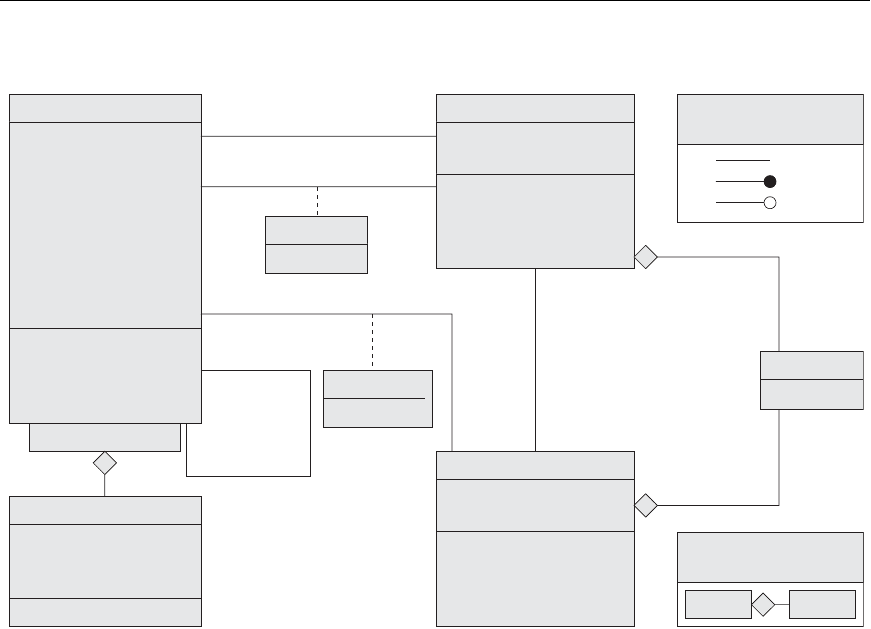
Figure 7.15
ER diagrams for the company schema, with structural con-
straints specified using (min, max) notation and role names.
14
In some notations, particularly those used in object modeling methodologies such as UML, the (min,
max) is placed on the opposite sides to the ones we have shown. For example, for the WORKS_FOR
relationship in Figure 7.15, the (1,1) would be on the DEPARTMENT side, and the (4,N) would be on the
EMPLOYEE side. Here we used the original notation from Abrial (1974).
max relationship instances in R at any point in time. In this method, min = 0 implies partial participation,
whereas min > 0 implies total participation.
Figure 7.15 displays the
COMPANY database schema using the (min, max) notation.
14
Usually, one uses
either the cardinality ratio/single-line/double-line notation or the (min, max) notation. The (min, max)
226 Chapter 7 Data Modeling Using the Entity-Relationship (ER) Model
supervisee
Name: Name_dom
Fname
Minit
Lname
Ssn
Bdate: Date
Sex: {M,F}
Address
Salary
4..*
1..*
1..* *
*
1..1
1..1
1..1
1..1
1..*
0..1
0..*
0..*
age
change_department
change_projects
. . .
Sex: {M,F}
Birth_date: Date
Relationship
DEPENDENT
. . .
0..1
supervisor
Dependent_name
EMPLOYEE
Name
Number
add_employee
number_of_employees
change_manager
. . .
DEPARTMENT
Name
Number
add_employee
add_project
change_manager
. . .
PROJECT
Start_date
MANAGES
CONTROLS
Hours
WORKS_ON
Name
LOCATION
1..1
0..*
0..1
Multiplicity
Notation in OMT:
Aggregation
Notation in UML:
Whole Part
WORKS_FOR
Figure 7.16
The COMPANY conceptual schema
in UML class diagram notation.
notation is more precise, and we can use it to specify some structural constraints for
relationship types of higher degree. However, it is not sufficient for specifying some
key constraints on higher-degree relationships, as discussed in Section 7.9.
Figure 7.15 also displays all the role names for the
COMPANY database schema.
7.8 Example of Other Notation:
UML Class Diagrams
The UML methodology is being used extensively in software design and has many
types of diagrams for various software design purposes. We only briefly present the
basics of UML class diagrams here, and compare them with ER diagrams. In some
ways, class diagrams can be considered as an alternative notation to ER diagrams.
Additional UML notation and concepts are presented in Section 8.6, and in Chapter
10. Figure 7.16 shows how the
COMPANY ER database schema in Figure 7.15 can be
displayed using UML class diagram notation. The entity types in Figure 7.15 are
modeled as classes in Figure 7.16. An entity in ER corresponds to an object in UML.
7.8 Example of Other Notation: UML Class Diagrams 227
In UML class diagrams, a class (similar to an entity type in ER) is displayed as a box
(see Figure 7.16) that includes three sections: The top section gives the class name
(similar to entity type name); the middle section includes the attributes; and the
last section includes operations that can be applied to individual objects (similar to
individual entities in an entity set) of the class. Operations are not specified in ER
diagrams. Consider the
EMPLOYEE class in Figure 7.16. Its attributes are Name, Ssn,
Bdate, Sex, Address, and Salary. The designer can optionally specify the domain of
an attribute if desired, by placing a colon (:) followed by the domain name or
description, as illustrated by the
Name, Sex, and Bdate attributes of EMPLOYEE in
Figure 7.16. A composite attribute is modeled as a structured domain, as illustrated
by the
Name attribute of EMPLOYEE. A multivalued attribute will generally be mod-
eled as a separate class, as illustrated by the
LOCATION class in Figure 7.16.
Relationship types are called associations in UML terminology, and relationship
instances are called links.A binary association (binary relationship type) is repre-
sented as a line connecting the participating classes (entity types), and may option-
ally have a name. A relationship attribute, called a link attribute, is placed in a box
that is connected to the association’s line by a dashed line. The (min, max) notation
described in Section 7.7.4 is used to specify relationship constraints, which are
called multiplicities in UML terminology. Multiplicities are specified in the form
min..max, and an asterisk (
*
) indicates no maximum limit on participation.
However, the multiplicities are placed on the opposite ends of the relationship when
compared with the notation discussed in Section 7.7.4 (compare Figures 7.15 and
7.16). In UML, a single asterisk indicates a multiplicity of 0..
*
, and a single 1 indi-
cates a multiplicity of 1..1. A recursive relationship (see Section 7.4.2) is called a
reflexive association in UML, and the role names—like the multiplicities—are
placed at the opposite ends of an association when compared with the placing of
role names in Figure 7.15.
In UML, there are two types of relationships: association and aggregation.
Aggregation is meant to represent a relationship between a whole object and its
component parts, and it has a distinct diagrammatic notation. In Figure 7.16, we
modeled the locations of a department and the single location of a project as aggre-
gations. However, aggregation and association do not have different structural
properties, and the choice as to which type of relationship to use is somewhat sub-
jective. In the ER model, both are represented as relationships.
UML also distinguishes between unidirectional and bidirectional associations (or
aggregations). In the unidirectional case, the line connecting the classes is displayed
with an arrow to indicate that only one direction for accessing related objects is
needed. If no arrow is displayed, the bidirectional case is assumed, which is the
default. For example, if we always expect to access the manager of a department
starting from a
DEPARTMENT object, we would draw the association line represent-
ing the
MANAGES association with an arrow from DEPARTMENT to EMPLOYEE.In
addition, relationship instances may be specified to be ordered. For example, we
could specify that the employee objects related to each department through the
WORKS_FOR association (relationship) should be ordered by their Salary attribute
228 Chapter 7 Data Modeling Using the Entity-Relationship (ER) Model
value. Association (relationship) names are optional in UML, and relationship
attributes are displayed in a box attached with a dashed line to the line representing
the association/aggregation (see
Start_date and Hours in Figure 7.16).
The operations given in each class are derived from the functional requirements of
the application, as we discussed in Section 7.1. It is generally sufficient to specify the
operation names initially for the logical operations that are expected to be applied
to individual objects of a class, as shown in Figure 7.16. As the design is refined,
more details are added, such as the exact argument types (parameters) for each
operation, plus a functional description of each operation. UML has function
descriptions and sequence diagrams to specify some of the operation details, but
these are beyond the scope of our discussion. Chapter 10 will introduce some of
these diagrams.
Weak entities can be modeled using the construct called qualified association (or
qualified aggregation) in UML; this can represent both the identifying relationship
and the partial key, which is placed in a box attached to the owner class. This is illus-
trated by the
DEPENDENT class and its qualified aggregation to EMPLOYEE in
Figure 7.16. The partial key
Dependent_name is called the discriminator in UML ter-
minology, since its value distinguishes the objects associated with (related to) the
same
EMPLOYEE. Qualified associations are not restricted to modeling weak enti-
ties, and they can be used to model other situations in UML.
This section is not meant to be a complete description of UML class diagrams, but
rather to illustrate one popular type of alternative diagrammatic notation that can
be used for representing ER modeling concepts.
7.9 Relationship Types of Degree
Higher than Two
In Section 7.4.2 we defined the degree of a relationship type as the number of par-
ticipating entity types and called a relationship type of degree two binary and a rela-
tionship type of degree three ternary. In this section, we elaborate on the differences
between binary and higher-degree relationships, when to choose higher-degree ver-
sus binary relationships, and how to specify constraints on higher-degree relation-
ships.
7.9.1 Choosing between Binary and Ternary
(or Higher-Degree) Relationships
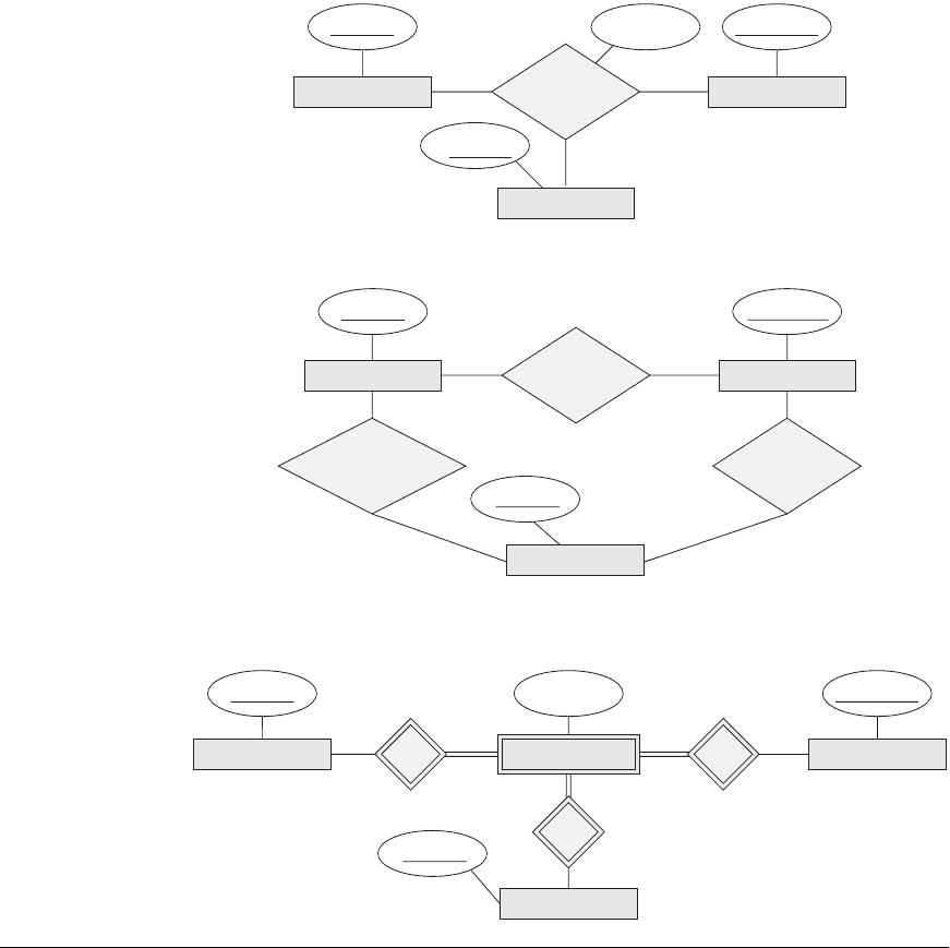
The ER diagram notation for a ternary relationship type is shown in Figure 7.17(a),
which displays the schema for the
SUPPLY relationship type that was displayed at
the entity set/relationship set or instance level in Figure 7.10. Recall that the rela-
tionship set of
SUPPLY is a set of relationship instances (s, j, p), where s is a
SUPPLIER who is currently supplying a PART p to a PROJECT j. In general, a rela-
tionship type R of degree n will have n edges in an ER diagram, one connecting R to
each participating entity type.
7.9 Relationship Types of Degree Higher than Two 229
(a)
SUPPLY
Sname
Part_no
SUPPLIER
Quantity
PROJECT
PART
Proj_name
(b)
(c)
Part_no
PART
N
Sname
SUPPLIER
Proj_name
PROJECT
N
Quantity
SUPPLY
N1
Part_no
MN
CAN_SUPPLY
N
M
Sname
SUPPLIER
Proj_name
PROJECT
USES
PART
M
N
SUPPLIES
SP
SPJSS
1
1
Figure 7.17
Ternary relationship types. (a) The SUPPLY
relationship. (b) Three binary relationships
not equivalent to SUPPLY. (c) SUPPLY
represented as a weak entity type.
Figure 7.17(b) shows an ER diagram for three binary relationship types
CAN_SUPPLY, USES, and SUPPLIES. In general, a ternary relationship type repre-
sents different information than do three binary relationship types. Consider the
three binary relationship types
CAN_SUPPLY, USES, and SUPPLIES. Suppose that
CAN_SUPPLY,between SUPPLIER and PART, includes an instance (s, p) whenever
supplier s can supply part p (to any project);
USES,between PROJECT and PART,
includes an instance (j, p) whenever project j uses part p; and
SUPPLIES, between
SUPPLIER and PROJECT, includes an instance (s, j) whenever supplier s supplies
230 Chapter 7 Data Modeling Using the Entity-Relationship (ER) Model
some part to project j. The existence of three relationship instances (s, p), (j, p), and
(s, j) in
CAN_SUPPLY, USES, and SUPPLIES, respectively, does not necessarily imply
that an instance (s, j, p) exists in the ternary relationship
SUPPLY, because the
meaning is different. It is often tricky to decide whether a particular relationship
should be represented as a relationship type of degree n or should be broken down
into several relationship types of smaller degrees. The designer must base this
decision on the semantics or meaning of the particular situation being represented.
The typical solution is to include the ternary relationship plus one or more of the
binary relationships, if they represent different meanings and if all are needed by the
application.
Some database design tools are based on variations of the ER model that permit
only binary relationships. In this case, a ternary relationship such as
SUPPLY must
be represented as a weak entity type, with no partial key and with three identifying
relationships. The three participating entity types
SUPPLIER, PART, and PROJECT
are together the owner entity types (see Figure 7.17(c)). Hence, an entity in the weak
entity type
SUPPLY in Figure 7.17(c) is identified by the combination of its three
owner entities from
SUPPLIER, PART, and PROJECT.
It is also possible to represent the ternary relationship as a regular entity type by
introducing an artificial or surrogate key. In this example, a key attribute
Supply_id
could be used for the supply entity type, converting it into a regular entity type.
Three binary N:1 relationships relate
SUPPLY to the three participating entity types.
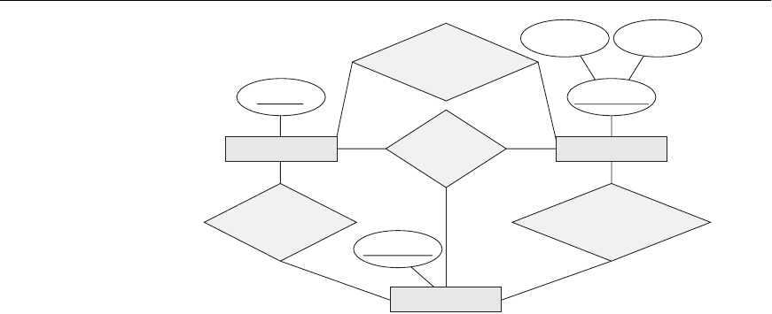
Another example is shown in Figure 7.18. The ternary relationship type
OFFERS
represents information on instructors offering courses during particular semesters;
hence it includes a relationship instance (i, s, c) whenever
INSTRUCTOR i offers
COURSE c during SEMESTER s. The three binary relationship types shown in
Figure 7.18 have the following meanings:
CAN_TEACH relates a course to the
instructors who can teach that course,
TAUGHT_DURING relates a semester to the
instructors who taught some course during that semester, and
OFFERED_DURING
Cnumber
CAN_TEACH
Lname
INSTRUCTOR
Sem_year
YearSemester
SEMESTER
OFFERED_DURING
COURSE
OFFERS
TAUGHT_DURING
Figure 7.18
Another example of ternary versus
binary relationship types.
7.9 Relationship Types of Degree Higher than Two 231
Dept_date
DateDepartment
RESULTS_IN
Name
CANDIDATE
Cname
COMPANY
INTERVIEW
JOB_OFFER
CCI
Figure 7.19
A weak entity type INTERVIEW
with a ternary identifying rela-
tionship type.
relates a semester to the courses offered during that semester by any instructor.
These ternary and binary relationships represent different information, but certain
constraints should hold among the relationships. For example, a relationship
instance (i, s, c) should not exist in
OFFERS unless an instance (i, s) exists in
TAUGHT_DURING, an instance (s, c) exists in OFFERED_DURING, and an instance (i,
c) exists in
CAN_TEACH. However, the reverse is not always true; we may have
instances (i, s), (s, c), and (i, c) in the three binary relationship types with no corre-
sponding instance (i, s, c) in
OFFERS. Note that in this example, based on the mean-
ings of the relationships, we can infer the instances of
TAUGHT_DURING and
OFFERED_DURING from the instances in OFFERS, but we cannot infer the
instances of
CAN_TEACH; therefore, TAUGHT_DURING and OFFERED_DURING are
redundant and can be left out.
Although in general three binary relationships cannot replace a ternary relationship,
they may do so under certain additional constraints. In our example, if the
CAN_TEACH relationship is 1:1 (an instructor can teach one course, and a course
can be taught by only one instructor), then the ternary relationship
OFFERS can be
left out because it can be inferred from the three binary relationships
CAN_TEACH,
TAUGHT_DURING, and OFFERED_DURING. The schema designer must analyze the
meaning of each specific situation to decide which of the binary and ternary rela-
tionship types are needed.
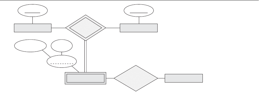
Notice that it is possible to have a weak entity type with a ternary (or n-ary) identi-
fying relationship type. In this case, the weak entity type can have several owner
entity types. An example is shown in Figure 7.19. This example shows part of a data-
base that keeps track of candidates interviewing for jobs at various companies, and
may be part of an employment agency database, for example. In the requirements, a
candidate can have multiple interviews with the same company (for example, with
different company departments or on separate dates), but a job offer is made based
on one of the interviews. Here,
INTERVIEW is represented as a weak entity with two
owners
CANDIDATE and COMPANY, and with the partial key Dept_date.An
INTERVIEW entity is uniquely identified by a candidate, a company, and the combi-
nation of the date and department of the interview.
