Davim J. Paulo (editor). Machining. Fundamentals and Recent Advances
Подождите немного. Документ загружается.

282 M.J. Jackson
increased fluidity that accompanies melting. A random distribution of vacancies is
also consistent with the increase in entropy observed on melting. Eyring’s theory
of fluid flow was initially termed the hole theory of fluid flow but later became
known as the significant structure theory, which is the title of Eyring–Jhon book
[25]. According to this theory the vacancies in a liquid move through a sea of
molecules. Eyring’s theory of liquid flow is mentioned here since it explains why
the flow of a liquid approximates the flow of metal passed a tool in chip forma-
tion. In this case microcracks (voids) move through a sea of crystalline solid.
10.3 Size Effects in Micromachining
It is appropriate at this point to mention that an alternative explanation for the
increase in hardness that occurs when the indentation size is reduced in metals has
recently been introduced [27–38]. It is based on the fact that there is an increase in
the strain gradient with a reduction in indentation size. This has been extended by
Dinesh et al. [39] to explain the size effect in machining. In the Dinesh et al. [39]
analysis the size effect in hardness is related to that in cutting by assuming the von
Mises criterion is applicable. Based on the experiments of Merchant, it is evident
that this is not applicable in steady-state chip formation.
In this strain gradient theory two types of dislocations are proposed: geometri-
cally necessary dislocations (
ρ
g
) that are responsible for work hardening and sta-
tistically stored dislocations (
ρ
S
) that are affected by a strain gradient. When
ρ
g
>>
ρ
S
conventional plasticity pertains (strain rate unimportant) but when
ρ
g
<<
ρ
S
a constitutive equation including strain rate should be included. The impression
one obtains in reading Dinesh et al. [39] is that the strain gradient approach is
uniquely responsible for the size effect in cutting. In their concluding remarks it is
suggested that it should be possible to verify the validity of the strain rate formula-
tion by experiments designed to test predictions of this approach. This has not yet
been done and until it is it will not be possible to determine whether the influence
of strain rate is significant in chip formation applications. In any case, it is be-
lieved that the explanation presented here based on the influence of defects and
normal stress on the shear plane is sufficiently well supported by the experiments
described that it should not be considered insignificant.
10.4 Nanomachining
Nanomachining can be classified into four categories:
• Deterministic mechanical nanometric machining. This method utilizes
fixed and controlled tools, which can specify the profiles of three-dimen-
sional components by a well-defined tool surface and path. The method can
remove materials in amounts as small as tens of nanometres. It includes
typically diamond turning, micro milling and nano/micro grinding, etc.;
Micro and Nanomachining 283
• Loose abrasive nanometric machining. This method uses loose abrasive
grits to removal a small amount materials. It consists of polishing, lapping
and honing, etc.
• Non-mechanical nanometric machining: focussed ion beam machining,
micro-EDM, and excimer laser machining; and
• Lithographic methods, which employ masks to specify the shape of the
product. Two-dimensional shapes are the main outcome; severe limitations
occur when three-dimensional products are attempted. This category
mainly includes X-ray lithography, LIGA and electron beam lithography.
Mechanical nanometric machining has more advantages than other methods since
it is capable of machining complex 3D components in a controllable way. The
machining of complex surface geometry is just one of the future trends in
nanometric machining, which is driven by the integration of multiple functions in
one product. For instance, the method can be used to machine micromoulds and
dies with complex geometric features and high dimensional and form accuracy,
and even nanometric surface features. The method is indispensable to manufactur-
ing complex micro and miniature structures, components and products in a variety
of engineering materials. This section focusses on nanometric cutting theory,
methods and its implementation and application perspectives [40–44].
10.4.1 Nanometric Machining
Single-point diamond turning and ultra-precision grinding are two major nanomet-
ric machining approaches. They are both capable of producing extremely fine cuts.
Single-point diamond turning has been widely used to machine non-ferrous metals
such as aluminium and copper. An undeformed chip thickness about 1 nm is ob-
served in diamond turning of electroplated copper [45]. Diamond grinding is an
important process for the machining of brittle materials such as glasses and ceram-
ics to achieve nanometre levels of tolerances and surface finish. A repeatable opti-
cal quality surface roughness (surface finish < 10 nm Ra) has been obtained in
nanogrinding of hard steel by Stephenson et al. using 76
μm grit CBN wheel on
the ultra-precision grinding machine tool [46]. Recently, diamond fly-cutting and
diamond milling have been developed for machining non-rotational non-
symmetric geometry, which has enlarged the product spectrum of nanometric
machining [47]. In addition the utilization of ultra-fine grain hard metal tools and
diamond coated microtools represents a promising alternative for microcutting of
even hardened steel [48].
Early applications of nanometric machining are in the mass production of some
high-precision parts for microproducts or microsystems. In fact, microproducts, or
microsystems, will be the first path that enables nanoproducts to enter the market-
place since microproducts, or microsystems, have been dominating nanotechnol-
ogy application markets worldwide [49]. It is also anticipated that requirements
for microproducts will increase worldwide. It is very interesting to see that the
information technology (IT) peripheral market is still the biggest market for mi-
croproducts. In 2005, the total turnover of microproducts reached US $38 billion,
which is twice the total turnover in 2000. Nanometric machining can be applied in
284 M.J. Jackson
bulk machining of silicon, aluminium substrates for computer memory disks, etc.
In other areas such as biomedical, automotive, household and telecommunications
the total turnovers of microproducts are still steadily growing. Nanometric ma-
chining is also very promising in the production of sensors, accelerometer, actua-
tors, micro-mirror, fibre-optic connectors and microdisplays. In fact applications
of nanoproducts will enhance the performance of microproducts in terms of sensi-
tivity, selectivity and stability [50]. However, by 2006, IT is expected to lose this
predominant position owing to new micro-electro-mechanical systems (MEMS)-
based applications in sectors such as biotechnology and communication (optical
and radiofrequency switching, for example, will become a major growth area)
[51]. Nanometric machining still has priority in this application area. The micro-
products are normally integrated products of some electronics, mechanical parts
and optical parts while in miniature or microscale dimensions. In fact only a small
number of microproducts rely solely on electronics. The mechanical and optical
parts are of significant importance for microproducts. The indispensable advan-
tage of nanometric machining is its applicability to manufacture complex three-
dimensional (3D) components/devices including micromoulds, dies and emboss-
ing tooling for cheap mass production of optical and mechanical parts. Therefore,
it is undoubtedly one of the major enabling technologies for commercialization of
nanotechnology in the future.
10.4.2 Theoretical Basis of Nanomachining
Scientific study of nanometric machining has been undertaken since the late
1990s. Much attention has been paid to its study, especially with the advance of
nanotechnology [52]. This scientific study will result in the formation of the theo-
retical basis of nanometric machining, which will enable better understanding of
nanometric machining physics and the development of controllable techniques to
meet the advanced requirements of nanotechnology and nanoscience.
10.4.2.1 Cutting Force and Energy
In nanomanufacturing, the cutting force and cutting energy are important issues.
They are important physical parameters for understanding cutting phenomena as
they clearly reflect the chip removal process. From the aspect of atomic structures
cutting forces are the superposition of the interactions forces between workpiece
atoms and cutting tool atoms. Specific energy is an intensive quantity that charac-
terizes the cutting resistance offered by a material [53]. Ikawa et al. and Luo et al.
have acquired the cutting forces and cutting energy by molecular dynamics simu-
lations [52–55]. Moriwaki and Lucca have carried out experiments to measure the
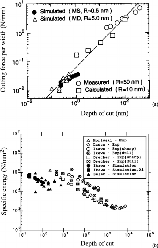
cutting forces in nanometric machining [52]. Figure 10.7 shows the simulation and
experimental results in nanometric cutting. Figure 10.7(a) illustrates the linear
relation that exists between the cutting forces per unit width and the depth of cut in
both simulations and experiments. The cutting forces per width increase with
increasing depth of cut.
The difference in the cutting force between the simulations and the experi-
ments is caused by the different cutting edge radii applied in the simulations. In
Micro and Nanomachining 285
Figure 10.7. Comparison of results between simulations and experiments: (a) cutting force
per width against depth of cut; (b) specific energy against depth of cut [52]
nanometric machining the cutting edge radius plays an important role since the
depth of cut is similar in scale. For the same depth of cut higher cutting forces are
needed for a tool with a large cutting edge radius compared with a tool with
a small cutting edge radius. The low cutting force per width is obviously the result
of fine cutting conditions, which will decrease the vibration of the cutting system
and thus improve the machining stability and also result in better surface rough-
ness. A linear relationship between the specific energy and the depth of cut can

286 M.J. Jackson
also be observed in Figure 10.7(b). The figure shows that the specific energy in-
creases with decreasing depth of cut, because the effective rake angle is different
for different depths of cut. For small depths of cut the effective rake angle will
increase with decreasing depth of cut. Large rake angle results in an increase in the
specific energy. This phenomenon is often called the size effect, which can be
clearly explained by the material data listed in Table 10.2, according to which, in
nanometric machining only point defects exist in the machining zone in a crystal,
so more energy is required to initiate an atomic crack or atomic dislocation. For
decreasing depth of cut the chance that the cutting tool will meet point defects
decreases, resulting in the increasing specific cutting energy.
If the machining unit is reduced to 1 nm, the workpiece material structure at the
machining zone may approach atomic perfection, so more energy will be required
to break the atomic bonds. On the other hand when the machining unit is higher
than 0.1
μm, the machining points will fall into the distribution distances of some
defects such as dislocations, cracks and grain boundaries. These pre-existing de-
fects will ease the deformation of workpiece material and result in a comparatively
low specific cutting energy. Nanometric cutting is also characterized by a high
ratio of the normal to the tangential component in the cutting force [53,
55], as the
depth of cut is very small in nanometric cutting, and the workpiece is mainly proc-
essed by the cutting edge. The compressive interactions will thus become domi-
nant in the deformation of the workpiece material, which will therefore result in an
increase of the friction force at the tool–chip interface and a relative high cutting
ratio. Usually the cutting force in nanometric machining is very difficult to meas-
ure due to its small amplitude compared with the noise (mechanical or electronic)
[52]. A piezoelectric dynamometer or load cell is used to measure the cutting
forces because of their high sensitivity and natural frequency [57].
10.4.2.2 Cutting Temperatures
In molecular dynamics simulation, the cutting temperature can be calculated under
the assumption that the cutting energy is totally transferred into cutting heat and
results in an increase of the cutting temperature and kinetic energy of system. The
lattice vibration is the major form of thermal motion of atoms. Each atom has
Table 10.2. Material properties under different machining units [56]
1 nm – 0.1 μm 0.1 μm – 10 μm 10 μm – 1 mm
Defects/impurities Point defect Dislocation/crack Crack/grain
boundary
Chip removal unit Atomic cluster Sub-crystal Multi-crystals
Brittle fracture limit 10
4
J/m
3
– 10
3
J/m
3
Atomic crack
10
3
J/m
3
– 10
2
J/m
3
Microcrack
10
2
J/m
3
– 10
1
J/m
3
Brittle crack
Shear failure limit 10
4
J/m
3
– 10
3
J/m
3
Atomic-dislocation
10
3
J/m
3
– 10
2
J/m
3
Dislocation slip
10
2
J/m
3
– 10
1
J/m
3
Shear deformation
Micro and Nanomachining 287
three degrees of freedom. According to the theorem of equipartition of energy, the
average kinetic energy of the system can be expressed as:
2
31
22
==
∑
_
kB i
i
ENkT m(V)
(10.14)
where
−
k
E is average kinetic energy in equilibrium state, K
B
is Boltzmann’s con-
stant, T is temperature, m
i
and V
i
are the mass and velocity of an atom, respec-
tively, and N is the number of atoms. The cutting temperature can be deduced as:
2
3
−
=
k
B
E
T
Nk
(10.15)
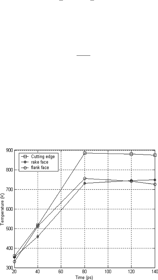
Figure 10.8 shows the variation of the cutting temperature on the cutting tool in
a molecular dynamics simulation of nanometric cutting of single-crystal alumin-
ium. The highest temperature is observed at the cutting edge, although the tem-
perature at the flank face is also higher than that at the rake face. The temperature
distribution suggests that a major heat source exists at the interface between the
cutting edge and the workpiece and that the heat is conducted from there to the
rest of the cutting zone in the workpiece and cutting tool. The reason is that, be-
cause most cutting action take place at the cutting edge of the tool, the dislocation
deformations of workpiece materials will transfer potential energy into the kinetic
energy and result in a rise in temperature. The comparatively high temperature at
Figure 10.8. Cutting temperature distribution of cutting tool in nanometric cutting (cutting
speed
=
20 m/s, depth of cut
=
1.5 nm, cutting edge radius
=
1.57 nm) [58]
288 M.J. Jackson
the tool flank face is obviously caused by friction between the tool flank face and
the workpiece. The released energy due to the elastic recovery of the machined
surface also contributes to the temperature increase at the tool flank face. Al-
though there is also friction between the tool rake face and the chip, the heat will
be taken away from the tool rake face by the removal of the chip.
Therefore, the temperature at the tool rake face is lower than that at the tool
cutting edge and tool flank face. The results shows that the cutting temperature in
diamond machining is quite low in comparison with that in conventional cutting,
due to the low cutting energy as well as the high thermal conductivity of diamond
and the workpiece material. The cutting temperature is considered to govern the
wear of a diamond tool in a molecular dynamics simulation study by Cheng et al.
[58]. More in-depth experimental and theoretical studies are needed to find the
quantitative relationship between the cutting temperature and tool wear, although
there is considerable evidence of chemical damage to diamond, in which tempera-
ture plays a significant role [52].
10.4.2.3 Chip Formation
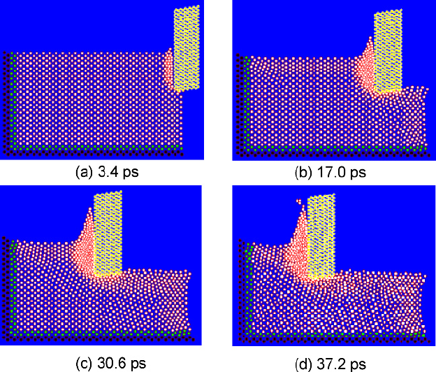
Chip formation and surface generation can be simulated by molecular dynamics
(MD) simulation. Figure 10.9 shows an MD simulation of a nanometric cutting
Figure 10.9. MD simulations of the nanometric machining process (cutting speed
=
20 m/s,
depth of cut
=
1.4 nm, cutting edge radius
=
0.35 nm) [58]
Micro and Nanomachining 289
process on single crystal aluminium. From Figure 11.6(a) it is observed that after
the initial plough of the cutting edge the workpiece atoms are compressed in the
cutting zone near to the rake face and the cutting edge. The disturbed crystal lat-
tices of the workpiece and even the initiation of dislocations can be observed in
Figure 10.9(b). Figure 10.9(c) shows that the dislocations have piled up to form a
chip. The chip is removed with the unit of an atomic cluster as shown in Fig-
ure 10.9(d). The lattice-disturbed workpiece material is observed on the machined
surface.
Based on this visualisation of the nanometric machining process, the mecha-
nism of chip formation and surface generation in nanometric cutting can be ex-
plained. Owing to the ploughing of the cutting edge, the attractive force between
the workpiece atoms and the diamond tool atoms becomes repulsive. Because the
cohesion energy of diamond atoms is much larger than that of Al atoms, the lattice
of the workpiece is compressed. When the strain energy stored in the compressed
lattice exceeds a specific level, the atoms begin to rearrange so as to release the
strain energy. When the energy is not sufficient to perform the rearrangement,
some dislocation activity is generated. Repulsive forces between compressed at-
oms in the upper layer and the atoms in the lower layer are increasing, so the up-
per atoms move along the cutting edge, and at the same time the repulsive forces
from the tool atoms cause the resistance for the upward chip flow to press the
atoms under the cutting line. With the movement of the cutting edge, some dislo-
cations move upward and disappear from the free surface as they approach the
surface.
This phenomenon corresponds to the process of the chip formation. As a result
of the successive generation and disappearance of dislocations, the chip seems to
be removed steadily. After the passing of the tool, the pressure at the flank face is
released. The layers of atoms move upwards and result in elastic recovery, so the
machined surface is generated. The conclusion can therefore be drawn that the
chip removal and machined surface generation have the nature of dislocation slip
movement inside the workpiece material crystal grains. In conventional cutting the
dislocations are initiated from existing defects between the crystal grains, which
will ease the movement of dislocation and result in smaller specific cutting forces
compared with that in nanometric cutting.
The height of the atoms on the surface layer of the machined surface creates the
surface roughness. For this, two-dimensional (2D) MD simulation R
a
can be used
to assess the machined surface roughness. The surface integrity parameters can
also be calculated based on the simulation results. For example, the residual stress
of the machined surface can be estimated by averaging the forces acting on the
atoms in a unit area on the upper layer of the machined surface. Molecular dynam-
ics (MD) simulation has been proved to be a useful tool for the theoretical study of
nanometric machining [59]. At present the MD simulation studies on nanometric
machining are limited by the computing memory size and speed of the computer.
It is therefore difficult to enlarge the dimensions of the current MD model on a
personal computer. In fact, the machined surface topography is produced as a
result of the copy of the tool profile on a workpiece surface that has a specific
motion relative to the tool. The degree of surface roughness is governed by both
the controllability of the machine tool motion (or the relative motion between tool
290 M.J. Jackson
and workpiece) and the transfer characteristics (or the fidelity) of the tool profile
to the workpiece [52]. A multi-scale analysis model, which can fully model the
machine tool and cutting tool motion, environmental effects and the tool–
workpiece interactions, is greatly needed to predict and control the nanometric
machining process in a determinative manner.
10.4.2.4 Minimum Undeformed Chip Thickness
The minimum undeformed chip thickness is an important issue in nanometric
machining because it is related to the ultimate machining accuracy. In principle
the minimum undeformed chip thickness will be determined by the minimum
atomic distance within the workpiece. However, in ultra-precision machining
practice, it strongly depends on the sharpness of the diamond cutting tool, the
capability of the ultra-precision machine tool and the machining environment.
The diamond turning experiments of non-ferrous work materials carried out at
Lawrence Livermoore National Laboratory (LLNL) show that a minimum unde-
formed chip thickness down to 1 nm is attainable with a specially prepared fine
diamond cutting tool on a highly reliable ultra-precision machine tool [45]. Based
on the tool wear simulation, the minimum undeformed chip thickness is further
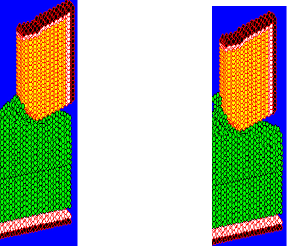
studied in this chapter. Figure 10.10 illustrates chip formation of single-crystal
aluminium with a tool cutting edge radius of 1.57 nm. No chip formation is ob-
served when the undeformed chip thickness is 0.25 nm, but the initial stage of
Figure 10.10. Study of minimum undeformed chip thickness by MD simulation [58]:
(a) undeformed chip thickness 0.25 nm, (b) undeformed chip thickness 0.26 nm
(a)
(b)

Micro and Nanomachining 291
chip formation is apparent when the undeformed chip thickness is 0.26 nm. In
nanometric cutting, as the depth of cut is very small, chip formation is related to
the force conditions at the cutting edge. Generally, chip formation is mainly
a function of tangential cutting force.
The normal cutting force makes little contribution to the chip formation since it
has the tendency to cause the atoms of the surface to penetrate the bulk of the
workpiece. In theory, the chip is formed under the condition that the tangential
cutting force is larger than the normal cutting force. The relationships between the
minimum undeformed chip thickness, the cutting edge radius, and the cutting
forces are studied via MD simulations. The results are highlighted in Table 10.3.
These data show that the minimum undeformed chip thickness is about one-third to
one-sixth of the tool cutting edge radius. The chip formation will be initiated when
the ratio of tangential cutting force to normal cutting force is larger than 0.92.
10.4.2.5 Critical Cutting Radius
It is widely accepted that the sharpness of the cutting edge of a diamond cutting
tool directly affects the machined surface quality. Previous MD simulations show
that, the sharper the cutting edge is, the smoother the machined surface becomes.
However, this conclusion is based on no tool wear. To study the real effects of
cutting edge radius, the MD simulations on nanometric cutting of single-crystal
aluminium are carried out using a tool wear model [59].
In these simulations the cutting edge radius of the diamond cutting tool varies
from 1.57 to 3.14 nm with depth of cut of 1.5, 2.2 and 3.1 nm respectively. The
cutting distance is fixed at 6 nm. The root-mean-square deviation of the machined
surface and mean stress on the cutting edge are listed in Table 10.4. Figure 10.11
shows a visualization of the simulated data, which clearly indicates that the sur-
face roughness increases with the decreasing cutting edge radius when the cutting
edge radius is smaller than 2.31 nm. The tendency is obviously caused by the
rapid tool wear when a cutting tool with a small cutting edge radius is used. How-
ever, when the cutting edge is larger than 2.31 nm, the cutting edge is under com-
pressive stress and no tool wear occurs. Therefore, it shows the same tendency that
the surface roughness increases with decreasing tool cutting edge radius, as in the
previous MD simulations.
Table 10.3. Minimum undeformed chip thickness against the tool cutting edge radius and
cutting forces [58]
Cutting edge radius (nm) 1.57 1.89 2.31 2.51 2.83 3.14
Minimum undeformed
chip thickness (nm)
0.26 0.33 0.42 0.52 0.73 0.97
Ratio of minimum unde-
formed chip thickness to
tool cutting edge radius
0.17 0.175 0.191 0.207 0.258 0.309
Ratio of tangential cutting
force to normal cutting
force
0.92 0.93 0.92 0.92 0.94 0.93