Bryan L. Programmable controllers. Theory and implementation
Подождите немного. Документ загружается.

729
CHAPTER
15
Process Controllers
and Loop Tuning
SECTION
4
PLC Process
Applications
Industrial Text & Video Company 1-800-752-8398
www.industrialtext.com
ESPPV
CV K
dE
dt
CV
K
dSP
dt
dPV
dt
CV
K
dSP
dt
K
dPV
dt
CV
tD t
Dt
DD t
=−
=+
=
−
+
=
−
+
=
=
=
() ( )
()
()
0
0
0
Since the set point is a constant value, the term
K
D
dSP
dt
()
will equal 0.
Therefore, the control variable is equal to:
CV K
dPV
dt
CV
tD t()
=− +
=()0
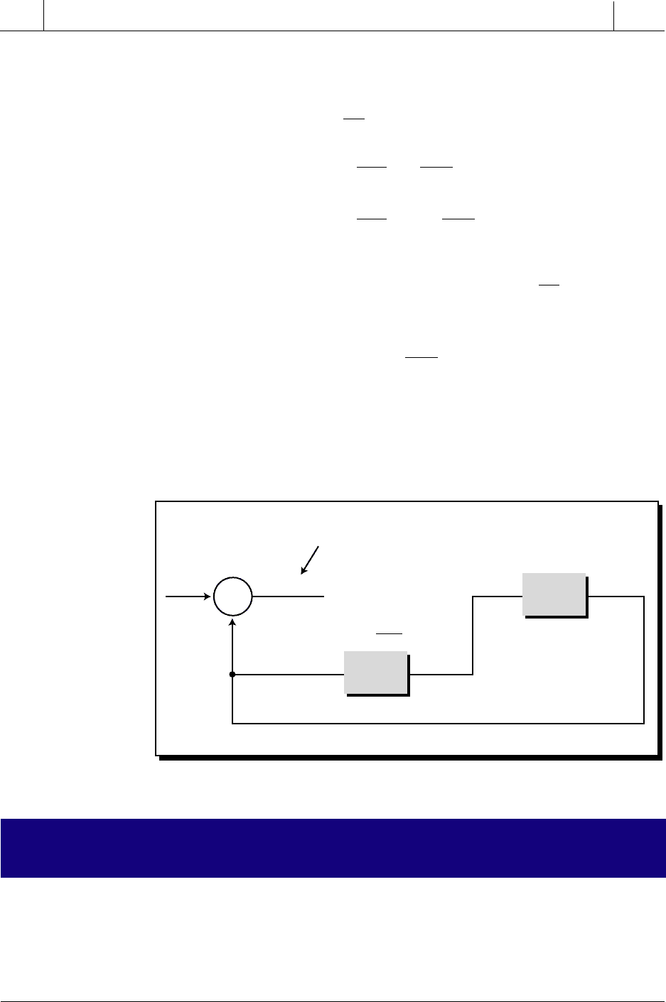
As shown in Figure 15-56, a modified derivative controller cannot be used by
itself because the error signal is not fed back to the controller for error
correction. Therefore, this type of derivative controller must be used in
combination with either a proportional or proportional-integral controller.
Figure 15-56. Modified derivative controller.
15-9 PROPORTIONAL-DERIVATIVE CONTROLLERS
(PD MODE)
Proportional-derivative controllers are composite controllers that com-
bine the actions of proportional and derivative controllers. A PD controller’s
output equation is represented as (see Figure 15-57):
Hp
Hc
–
K
P
E
=
SP
–
PV PVSP
+
–
Σ
PV
dPV
dt
Process will not correct error
since there is no feedback.
730
SECTION
4
PLC Process
Applications
Industrial Text & Video Company 1-800-752-8398
www.industrialtext.com
CHAPTER
15
Process Controllers
and Loop Tuning
For : (parallel)
series)
For (parallel)
(series)
dE
dt
CV K E K
dE
dt
CV
CV K E K K
dE
dt
CV
dPV
dt
CV K E K
dPV
dt
CV
CV K E K K
dPV
dt
CV
tP D t
tP PD t
tP D t
tP PD t
() ( )
() ( )
() ( )
() ( )
(
:
=+ +
=+ +
=− +
=− +
=
=
=
=
0
0
0
0
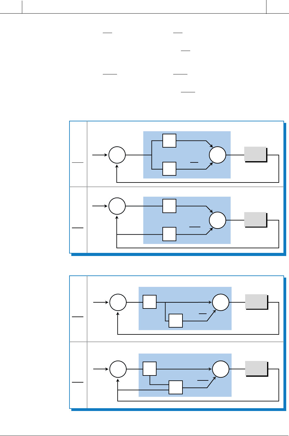
Figure 15-57. (a) Parallel and (b) series PD controllers.
(a) Parallel PD controller
EPVCVSP
+
+
+
–
Σ Σ
PV
P
D
K
P
E
K
D
EPVCVSP
+
+
+
–
Σ
Σ
PV
P
D
K
P
E
K
P
K
D
For
dE
dt
dE
dt
Hc
E
PVCV
SP
+
+
–
–
Σ
Σ
PV
P
D
K
P
E
For
dPV
dt
Hc
K
D
dPV
dt
dE
dt
(b) Series PD controller
For
dE
dt
Hc
Hc
EPVCVSP
+
+
–
–
Σ
Σ
PV
P
D
K
P
E
K
P
K
D
K
P
K
P
dPV
dt
For
dPV
dt
Hp
Hp
Hp
Hp
731
CHAPTER
15
Process Controllers
and Loop Tuning
SECTION
4
PLC Process
Applications
Industrial Text & Video Company 1-800-752-8398
www.industrialtext.com
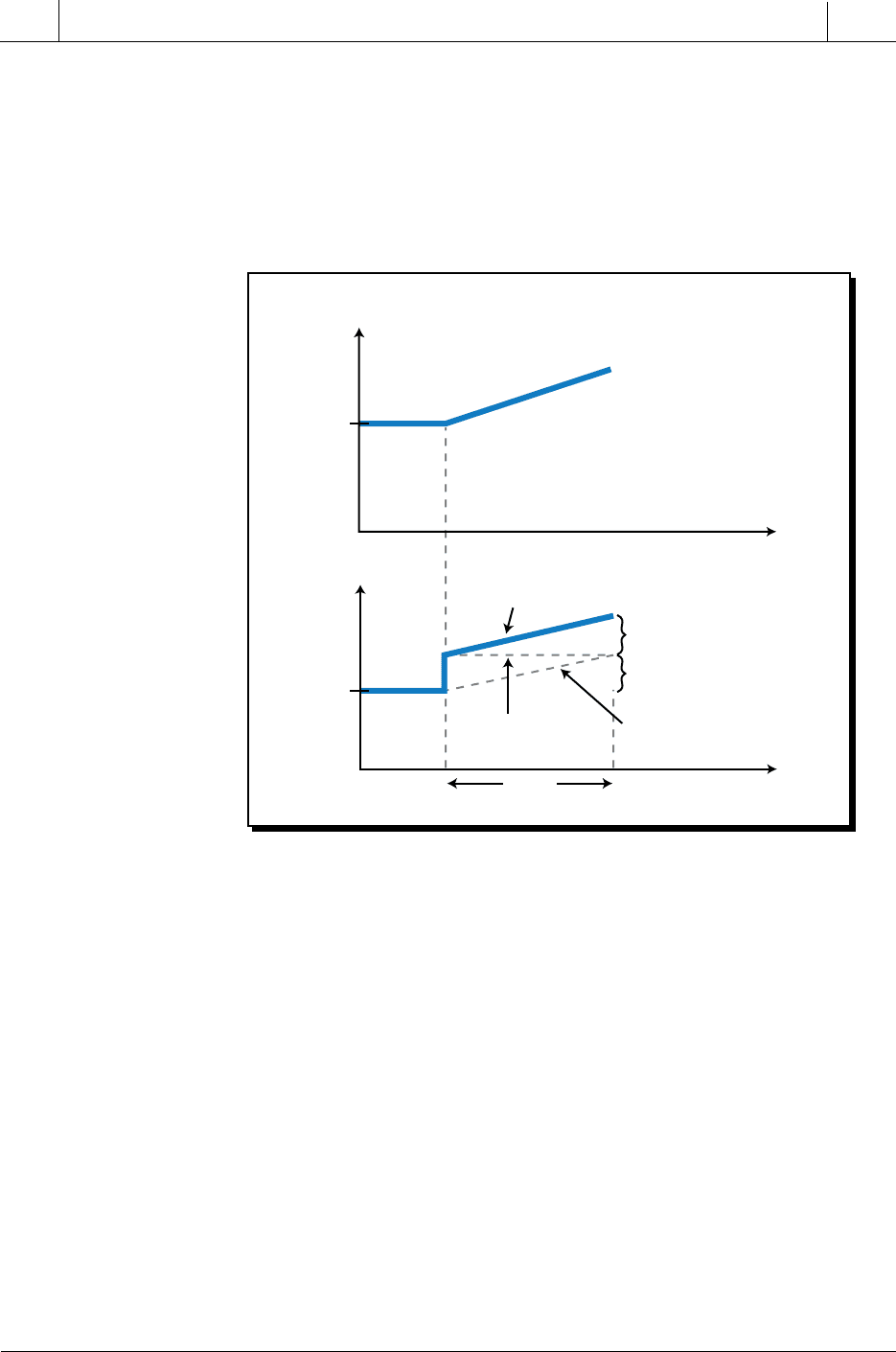
Figure 15-58. Proportional-derivative controller’s response to an error.
These equations are formed by adding the equations for the proportional and
derivative actions. Sometimes, the term K
D
is replaced with the term T
D
, since
both have their units in time (seconds or minutes). The term K
D
(or T
D
) in a
series PD controller (see Figure 15-58) indicates the time it takes for the
proportional action to equal the derivative action, in other words, for the
controller to repeat the derivative action.
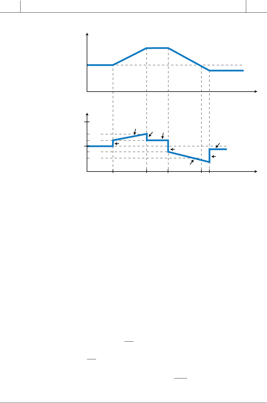
The derivative component of a PD controller provides a faster response than
just the proportional action alone, since it provides an immediate response
to an error change that behaves in ramp form (see Figure 15-59). The
proportional response to a ramping error is slower than the anticipatory
response of a derivative action. The proportional action increases the output
as it reads the error level. Since the proportional action only senses the
amount of error and not its rate of change, it does not anticipate the top error
value until that point is reached. A derivative action, on the other hand,
anticipates the error value because it evaluates the rate at which the error is
changing and, correspondingly, provides an extra amount of controller
output. Therefore, when the error changes in ramp form instead of step form,
the derivative gain compensates for the proportional control’s delay in action.
Although the derivative gain offsets the integral delay in a PD controller, it
does not eliminate the offset error at steady state, which is shown in Figure
15-59 at t
5
.
50%
CV
Error
T
D
t
t
+
–
E
= 0
Derivative
Component
Proportional
Component
Combined
Response
Proportional
K
P
=
K
D
Derivative
732
SECTION
4
PLC Process
Applications
Industrial Text & Video Company 1-800-752-8398
www.industrialtext.com
CHAPTER
15
Process Controllers
and Loop Tuning
The derivative action in a PD controller adds stability to a closed-loop
system by reducing the amount of overshoot and undershoot in the system’s
response. The derivative component acts as a “brake” in the system, slowing
the proportional response as the process variable approaches its set point.
The speed of response, however, also slows down. To observe this braking
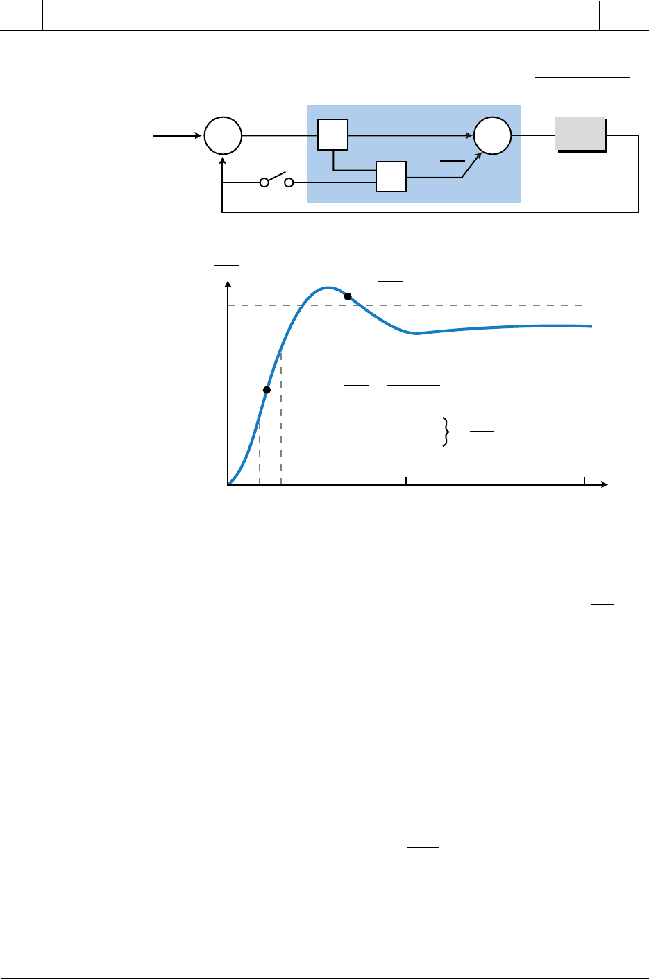
effect, let’s examine the reaction of the closed-loop system in Figure 15-60
to a unit step. This is a second-order system with a proportional gain of K
P
=
8 and no derivative gain (switch open). The addition of derivative action to
this system will help to stabilize the overshoot and undershoot of the response
to a change in error.
If the set point in Figure 15-60 changes, the proportional controller will try to
bring the error to zero by making PV equal SP. The error at the start (t
0
) is 1,
and as PV approaches SP, this error becomes smaller. In this proportional
action, the controller output is positive (direct acting), which makes the PV
value become more positive. The slope of PV is also positive, as seen at point A.
This positive value of
dPV
dt
can be approximated as shown in Figure 15-60.
If derivative action were present in this system (switch closed), then the
value of
dPV
dt
would be negative:
PV K E K K
dPV
dt
PV
tP PD t() ( )
=− +
=0
100%
50%
0%
+
E
= 0
–
CV
t
t
Error
t
1
t
2
t
3
t
4
t
5
70%
60%
40%
30%
+P
+P
–D
–P
–P
+D
–D
–D
Figure 15-59. PD responses to step changes in error.
733
CHAPTER
15
Process Controllers
and Loop Tuning
SECTION
4
PLC Process
Applications
Industrial Text & Video Company 1-800-752-8398
www.industrialtext.com
Figure 15-60. Reaction of a closed-loop system to a unit step.
thus having the opposite sign of the proportional gain. Therefore, with
derivative action, the output of PV
(t)
(at point A) would be less than a pure
proportional controller without derivative action. In fact, a positive
dPV
dt
term
(slope) would make the derivative term in the PD system equation negative.
This indicates that the derivative action of the PD controller will brake the
response of the proportional action, therefore reducing the amount of over-
shoot. The same holds true when the slope is negative, which occurs when the
response of the pure proportional action starts to decrease (point B). When the
proportional response becomes negative, the derivative term becomes posi-
tive, thus braking the undershoot:
CV K E K K
dPV
dt
CV
KE KK
dPV
dt
CV
tP PD tb
PPD tb
() (@ )
(@)
()=−− −
+
=− + +
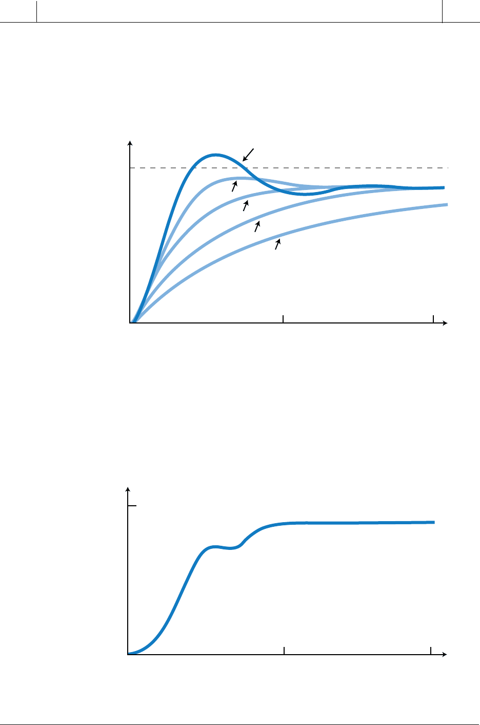
So, by adding the derivative action to this closed-loop system (switch closed
in block diagram), it is possible to reduce the overshoot and undershoot
through the braking effect of the derivative action. Figure 15-61 illustrates
Hp
EPVCVSP
+
+
–
–
Σ
Σ
PV
P
D
K
P
E
K
P
K
D
K
P
dPV
dt
dPV
dt
dPV
dt
PV
SP
dPV
dt
PV
2
–
PV
1
t
2
–
t
1
PV
2
>
PV
1
t
2
>
t
1
Hc
(
S
)
= 8
Hp
(
S
)
=
τ
1
= 10 min
τ
1
= 2.5 min
1
(10
s
+1)(2.5
s
+1)
10
t
1
t
0
t
2
20
1.0
0.0
PV
1
PV
2
A
B
is negative
=
is positive
⇒
t
(min)
734
SECTION
4
PLC Process
Applications
Industrial Text & Video Company 1-800-752-8398
www.industrialtext.com
CHAPTER
15
Process Controllers
and Loop Tuning
this closed-loop system for several values of derivative gain K
D
(or T
D
,
derivative time). As the gain of the derivative action increases, the over-
shoot and undershoot decrease. However, the system response also slows
down.
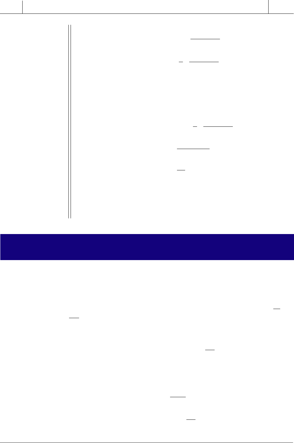
If a proportional-derivative controller has too much derivative gain, the
system response will start to look like the graph in Figure 15-62. This
indicates that the derivative action is no longer effective in restoring the
desired stability margin.
Figure 15-61. Closed-loop process response to a proportional-derivative controller for
several values of
K
D
.
1.0
0.0
10 20
t
(min)
PV
No derivative action
K
D
= 0
K
D
= 1
K
D
= 2.5
K
D
= 5
K
D
= 10
Figure 15-62. Process reponse of a proportional-derivative controller with too much
derivative gain.
1.0
0.0
10 20
t
(min)
PV

735
CHAPTER
15
Process Controllers
and Loop Tuning
SECTION
4
PLC Process
Applications
Industrial Text & Video Company 1-800-752-8398
www.industrialtext.com
EXAMPLE 15-9
The closed-loop system described in Examples 15-5 and 15-8 em-
ployed proportional and proportional-integral controllers, respec-
tively, to control a first-order system with a gain of 5 and a time constant
of
τ = 30 seconds. Given that the system utilizes a proportional-
derivative controller with a proportional gain of
K
P
= 8 and a derivative
gain of 2 minutes (120 seconds), find (a) the closed-loop transfer
function of the system and (b) the steady-state value of the response
to a step input (
1
s
).
S
OLUTION
(a) The transfer function of the process is:
Hp
s
s
()
=
+
5
30 1
The controller’s transfer function is:
Hc K K s
s
sPD
()
=+
=+8 120
Therefore, the closed-loop system transfer function is:
PV
SP
Hc Hp
Hc Hp
s
s
s
s
ss
ss
s
s
s
s
s
s
s
s
ss
s
s
()
()
() ()
() ()
=
+
=
+
(
)
(
)
[]
+
(
)
(
)
+
[]
=
(
)
(
)
+
=
(
)
(
)
=
+
+
+
+
+
+
+
+
+++
+
+
1
8 120
8 120 1
1
5
30 1
5
30 1
40 600
30 1
40 600
30 1
40 600
30 1
40 600 30 1
30 1
40 600
30
ss
s
s
s
s
+
+
+
(
)
(
)
=
+
+
1
41 630
30 1
40 600
41 630
(b) The system response to a step input change is represented by:
736
SECTION
4
PLC Process
Applications
Industrial Text & Video Company 1-800-752-8398
www.industrialtext.com
CHAPTER
15
Process Controllers
and Loop Tuning
PV SP
s
s
s
s
s
ss
() ()
=
+
+
=
+
+
40 600
41 630
1 40 600
41 630
Applying the final value theorem to this Laplace function yields the
following value:
lim lim
()
()
.
()
s
s
s
sPV s
s
s
s
→→
=
+
+
=
+
+
=
=
00
1 40 600
41 630
40 6000
41 6300
40
41
0 976
So, the final value of the process variable at steady state will be 0.976,
producing an offset error of 2.4%.
15-10 PROPORTIONAL-INTEGRAL-DERIVATIVE
CONTROLLERS (PID MODE)
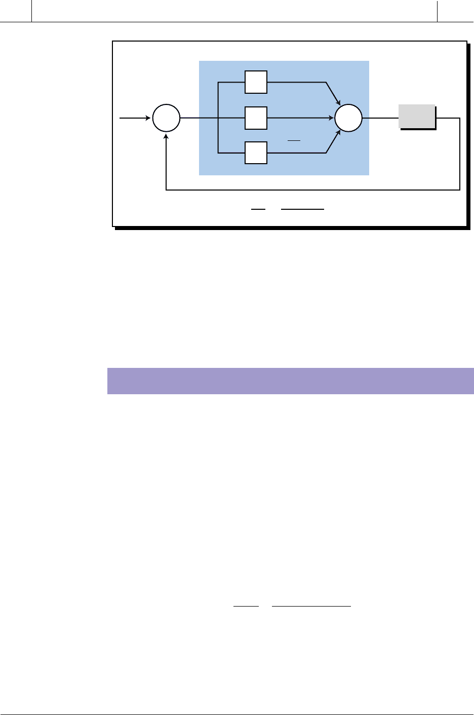
A proportional-integral-derivative (PID) controller combines the actions
of all three controller modes. A PID controller, also called a three-mode
controller, can be used to control almost any process that involves lags and
dead times. A PID controller can be arranged in either a series or parallel
configuration using either a standard or modified derivative action (
dE
dt
and
dPV
dt
, respectively). The basic expression for the process variable output for
a standard parallel PID controller (see Figure 15-63) is:
PV K E K Edt K
dE
dt
PV
tP I
t
Dt() ( )
=+ + +
∫
=
0
0
In Laplace form, this controller’s transfer function is represented as:
Hc
CV
E
K
K
s
Ks
s
s
s
P
I
D
()
()
()
=
=++
737
CHAPTER
15
Process Controllers
and Loop Tuning
SECTION
4
PLC Process
Applications
Industrial Text & Video Company 1-800-752-8398
www.industrialtext.com
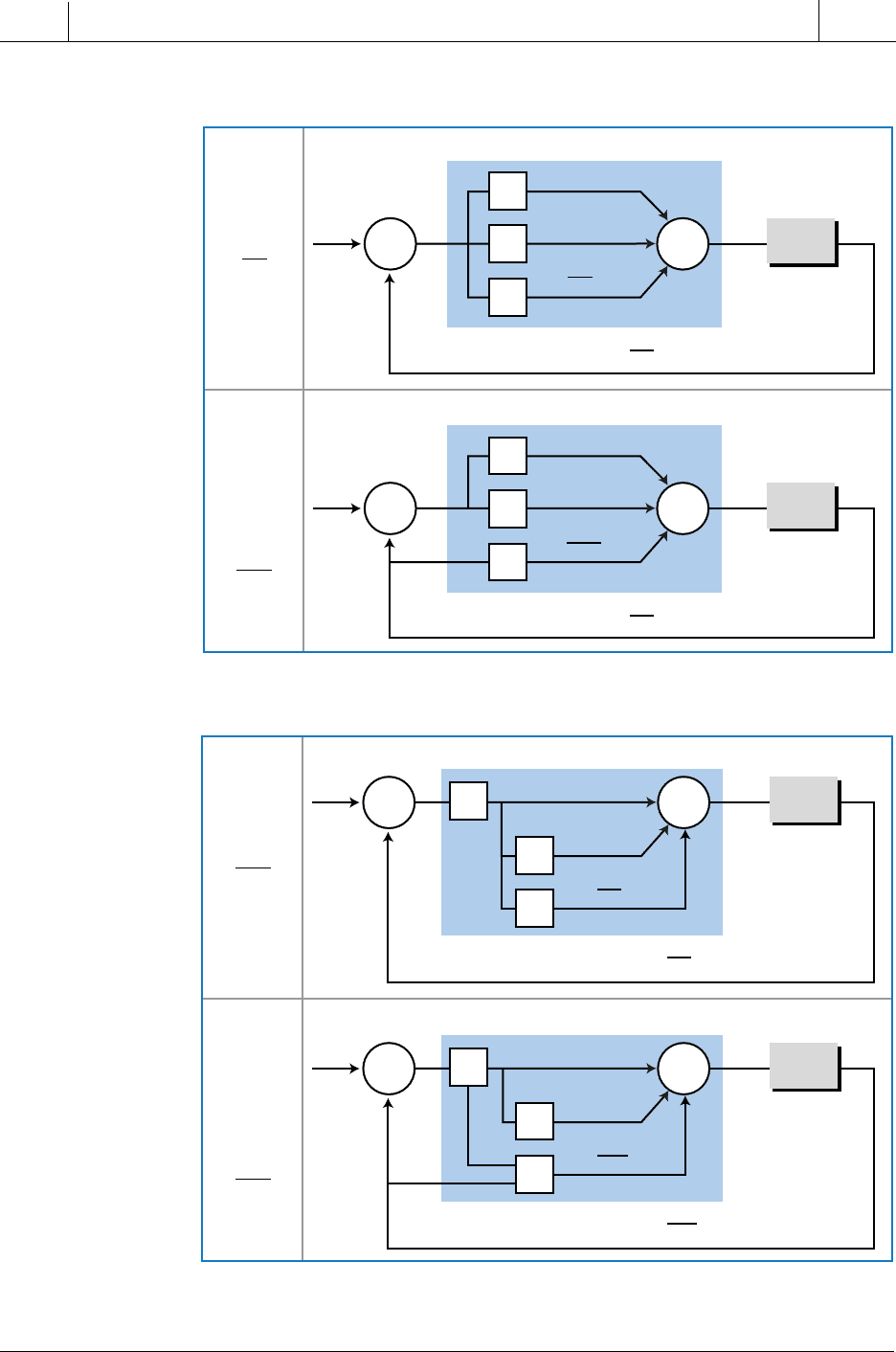
Figure 15-64 illustrates the serial and parallel system configurations for a
PID controller, along with their respective closed-loop equations.
PID control eliminates the offset of the proportional action through its
integral action and suppresses oscillation with its derivative action. When
properly tuned (see Section 15-12), a PID controller will smoothly regulate
the response of a complex system or process.
Figure 15-63. Standard parallel PID controller.
Hp
Hc
E
PVCV
SP
+
+
+
+
–
Σ
Σ
PV
D
I
P
K
P
E
K
D
dE
dt
PV
SP
HcHp
1 +
HcHp
=
K
I
∫
Edt
0
t
ORIGINS OF PID CONTROL
In this section, we will explain why the PID controller is the perfect
controller for a typical process. To illustrate the relationship between a PID
controller and a process, we will examine a typical second-order process
system. For computational purposes, a second-order system can be thought
of as including a first-order system, in order to determine what type of
controller will make the process in an open-loop system have a transfer
function equal to one. We will discuss this in more detail shortly.
It is very difficult to determine the exact transfer function (Hp
(s)
) of a real-life
process (i.e., a manufacturing process). However, it can be approximated by
a second-order system with two lag times and a dead time delay. In Laplace
form, this transfer function is defined as:
PV
CV
Ae
ss
s
s
ts
d
()
()
()()
=
++
−
ττ
12
11
The
e
–t s
d
term, the dead time delay, can be omitted from this equation,
since we know that this term only indicates that there is a shift in time in the
response. For practical purposes, the dead time will cause the response to
behave in the same manner, only displaced in time by the delay. So, for
738
SECTION
4
PLC Process
Applications
Industrial Text & Video Company 1-800-752-8398
www.industrialtext.com
CHAPTER
15
Process Controllers
and Loop Tuning
Figure 15-64. (a) Parallel and (b) serial PID controllers.
(a) Parallel PID controller
Standard
Derivative
dE
dt
Modified
Derivative
dPV
dt
Hc
E
PVCV
SP
+
+
+
+
–
Σ
Σ
PV
D
I
P
K
P
E
K
D
dE
dt
dE
dt
PV
(
t
)
=
K
P
E
+
K
I
∫
Edt
+
K
D
+
PV
(
t
=0)
Hc
E
PVCV
SP
+
+
–
+
–
Σ
Σ
PV
D
I
P
K
P
E
K
D
dPV
dt
(b) Serial PID controller
Standard
Derivative
dE
dt
Modified
Derivative
dPV
dt
Hc
E
PVCV
SP
+
+
+
+
–
Σ
Σ
PV
D
I
P
K
P
E
K
P
K
D
dE
dt
Hc
E
PVCV
SP
+
+
–
+
–
Σ
Σ
PV
D
I
P
K
P
E
K
P
K
D
dPV
dt
K
P
K
I
∫
Edt
0
t
K
I
∫
Edt
0
t
0
0
t
dE
dt
PV
(
t
)
=
K
P
E
+
K
I
∫
Edt
–
K
D
+
PV
(
t
=0)
t
0
dE
dt
PV
(
t
)
=
K
P
E
+
K
P
K
I
∫
Edt
+
K
P
K
D
+
PV
(
t
=0)
t
0
dPV
dt
PV
(
t
)
=
K
P
E
+
K
P
K
I
∫
Edt
–
K
P
K
D
+
PV
(
t
=0)
t
0
t
K
P
K
I
∫
Edt
0
t
K
P
K
I
∫
Edt
Hp
Hp
Hp
Hp
