Bednorz W. (ed.) Advances in Greedy Algorithms
Подождите немного. Документ загружается.

Greedy Algorithm: Exploring Potential of Link Adaptation Technique
in Wideband Wireless Communication Systems
181
2
[| ( ) | ]
mm mm
TBV E E
βε βε
=−
(12)
where E[⋅] denotes expectation operation; and
ε
m
denotes BER for the m-th user. Hence, if
TBV is large, the transmittable bits numbers for all the users vary much, and such method
cannot bring good fairness to the system. Low TBV denotes that the numbers for
transmittable bits for all the users are quite near, which means that such method is a fair
resource allocation solution.
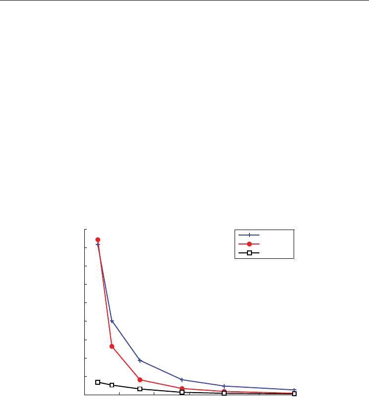
Transmittable bits variances for the 3 methods versus user number for SNR=15dB are shown
in Fig. 9. As the number of users increases, the average allocated bits number decreases, so
TBV is reduced. For the fixed method, the transmittable bit variance is quite high, which can
be explained by the fact that channel fading for different users varies greatly. As for the
ordered method, since fairness is guaranteed through allocating the same number of sub-
carriers according to CSI of all users, TBV is lower than the fixed method. But the variance is
still high, when there are 4 users in the system, TBV can reach more than 10000. The
proposed method can perform excellent in fairness. Fig. 9 indicates that it obtains much
lower TBV than the fixed method and the ordered method. When the number of users is 4,
TBV can be further reduced by about 80% compared to the ordered method.
0 5 10 15 20 25 30
0
0.5
1
1.5
2
2.5
3
3.5
4
4.5
x 10
4
User Number M
Transmission bit variance
Fixed
Ordered
Proposed
Fig. 9. Transmitted bits variance among users v. s. M for SNR=15dB
From the simulation results and analysis we can see that, the proposed method takes
advantage of Greedy algorithm for many times, and can obtain nice BER performance, so it
can provide required QoS guaranteeing. It can bring much larger throughput (more than
40%) than the fixed method. It performs a little worse than the ordered method, but when
fairness is concerned, the cost is worthy. The proposed method with application of Greedy
algorithm for many times can bring excellent fairness performance over the other methods.
It is recommended to be adopted for services with tight fairness requirement among all
users.
Advances in Greedy Algorithms
182
5. Application of greedy algorithm in OFDM relaying systems
The Greedy algorithm can be also adopted in OFDM relaying systems. In this section, we
carry out research into the adaptive bit and power allocation technique in relaying system.
Since there are several modes for relaying system, we take amplify-and-forward (AF) mode
for example.
5.1 AF-OFDM relaying system model
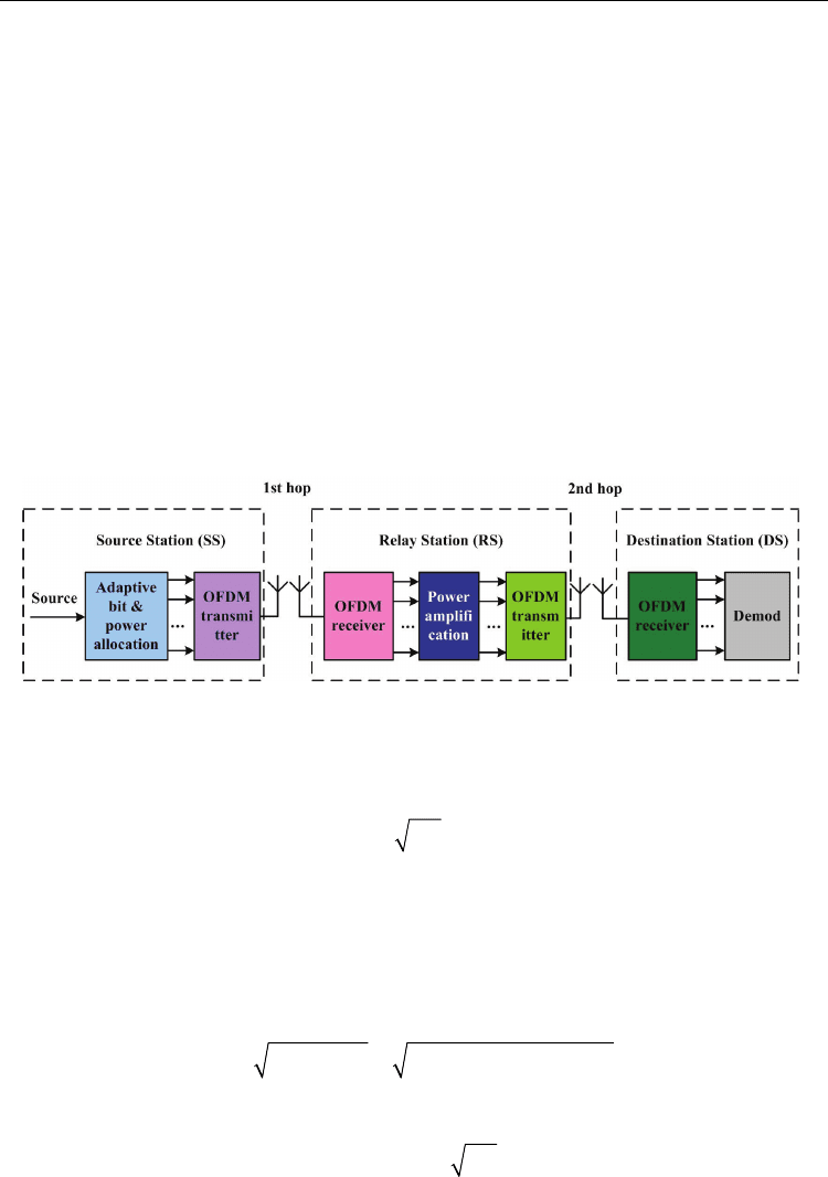
AF-OFDM relaying system model is shown in Fig. 10, where a two-hop system is considered
for its implementation advantages. In the first hop, source bits are modulated, and are
allocated with a certain power at source station (SS). Then the modulated signals construct
OFDM symbols, which are transmitted to relay station (RS). At RS, power amplification is
carried out after signals on all sub-carriers are obtained. In the second hop, these signals are
transmitted to the destination station (DS). After demodulation to the received signals on all
the sub-carriers, source bits are recovered finally. During both hops, signals experience
channel fading and AWGN. Channel transfer functions for the two hops are independent
with each other since the two hops happen between different transmitters and receivers on
different time slots.
Fig. 10. AF-OFDM relaying system model
We first introduce the basic model. Assume there are K sub-carriers in the OFDM system,
and the channel transfer function of the k-th sub-carrier in the i-th hop is H
i,k
. Then the first
hop can be expressed as:
1, 1, 1,kkkkk
RH PSn=+ (13)
where S
k
and P
1,k
denote the modulated signal and allocated power on the k-th sub-carrier,
respectively; E[|S
k
|
2
]=1; n
1,k
denotes AWGN with variance of
σ
1
2
; R
k
denotes the received
signal at RS.
Amplification is carried out at RS. Assume the amplification factor is ρ
k
. Therefore, the
average transmit power of the k-th sub-carrier at RS on the second hop is P
2,k
=|ρ
k
R
k
|
2
.
Hence, ρ
k
can be calculated as
222
2, 2, 1, 1, 1
/| | /[| | ]
kkk kkk
PR P H P
ρ
σ
== + (14)
The second hop can be expressed as:
2, 2, 1, 2, 1, 2, 1, 2,k kkk k k kk kk kk k k
D
HRnHH PSHnn
ρρρ
=+= + + (15)

Greedy Algorithm: Exploring Potential of Link Adaptation Technique
in Wideband Wireless Communication Systems
183
where D
k
denotes the received signal on the k-th sub-carrier at DS, and n
2,k
denotes AWGN
with variance of
σ
2
2
. In the section, we consider
σ
1
2
=
σ
2
2
=
σ
2
. From (15) we can obtain the
SNR of D
k
as follows:
22 222 2
1, 2, 1, 2, 1 2
[| | ]/[| | ]
kkkkkkk
HH P H
γ
ρρσσ
=+ (16)
We take adaptive bit allocation into account, i.e. modulation on all sub-carriers can be
adjusted according to the channel condition. We assume that L candidate modulations can
be selected, and every signal with the l-th (l=1, 2, …, L) modulation is loaded with b(l) bits.
The candidate modulations in the research and their throughputs are shown in Table 2. We
assume that the k-th sub-carrier adopts the l
k
-th modulation. Hence, the adaptive bit and
power allocation (ABPA) problem in a two-hop AF-OFDM relaying system is described as
how to allocate bits and power in the transmission (i.e. l
k
, P
1,k
and P
2,k
), so as to maximize
system throughput subject to BER requirement and power constraint. In the section, we
assume the target BER (BER
tgt
) to be 10
-3
. Hence
γ
k
should be higher than a certain threshold
so as to achieve BER
tgt
. We assume the threshold for the l
k
-th modulation is T(l
k
), which is
also provided in Table I for BER
tgt
=10
-3
.
v
Modulation Number of bits b(v) T(v) (dB)
0 No transmission 0 0
1 QPSK 2 9.78dB
2 16QAM 4 16.52dB
3 64QAM 6 22.52dB
4 256QAM 8 28.4
5 1024QAM 10 35.0
Table 2. Candidate modulation and parameters
Since power constraint may be different for different application scenarios, we research into
IPC problem and APC problem in the section, respectively.
5.2 ABPA problem and solutions with IPC
From the analysis above, the ABPA problem with IPC can be described as
1, 2,
,,
1
arg max ( )
kk k
K
k
lP P
k
bl
=
∑
(17)
subject to
1, 2,
1
1/ ( ) (a)
K
kk
k
KPP P
=
+≤
∑
(b)
ktgt
BER BER=
(18)
Equation (18a) denotes the IPC requirement, i.e. the instantaneous total power cannot be
larger than P. And (18b) illustrates BER requirement. From (16) and Table 2, (18b) can be
replaced by (19).

Advances in Greedy Algorithms
184
22 222 2
1, 2, 1, 2, 1 2
||/[|| ]()
kk kk k k k
HH P H Tl
ρρσσ
+= (19)
Assume that G
i,k
=|H
i,k
|/
σ
i
2
, (i=1,2). According to (14), we can further rewrite (19) as
1, 2, 1, 2, 1, 1, 2, 2,
/[ 1] ( )
kkkk kk kk k
GG PP GP G P Tl++=
(20)
Usually, such problem can be solved with Greedy algorithm [13], whose main concept is to
achieve the global optimal allocation with many local optimal allocations. During every
local optimal allocation, the least additional bits are allocated to the sub-carrier which
requires the least additional power to satisfy BER requirement. Such allocations continue
until the remaining power is not enough to support more bits. According to Table 2, the
least additional bit number for every allocation is 2 in the section.
Since the allocation of power relates to P
1,k
and P
2,k
, we discuss the problem for different
cases: 1) Adaptive PA at SS or RS; 2) Adaptive PA at SS and RS.
A. Adaptive PA at SS or RS
When P
2,k
is fixed and P
1,k
can be adjusted according to channel condition, we assume
2, 1,
1
1
,
K
R
SSSRS
kk
k
P
PPPPP
K
=
===−
∑
(21)
From (20), when the k-th sub-carrier adopts the l
k
-th modulation, we can get the required
power as follows.
1, 2 , 1, 2,
() ()[ 1]/ [ ()]
SS RS RS
kk k k k k k
P
lTlGP GGPTl=+ − (22)
Hence, in order to further load additional 2 bits on the k-th sub-carrier, the required
additional power is
1, 1,
(1) ()
SS SS SS
kkk kk
P
Pl PlΔ= +− (23)
According to Greedy algorithm, the sub-carrier with the minimum ΔP
k
SS
will be allocated
with 2 bits during every allocation. Such allocations will be terminated when the remaining
power is not enough to support more bits.
When P
1,k
is fixed and P
2,k
can be adjusted, we assume
1, 2,
1
,1/
K
SS RS SS
kk
k
P
PKPPPP
=
===−
∑
(24)
We take the similar measures to the scheme with adaptive PA at SS. In this case, when the k-
th sub-carrier adopts the l
k
-th modulation, the required power for the sub-carrier is as
follows.
2, 1, 2, 1,
() ()[ 1]/ [ ()]
RS SS SS
kk k k k k k
P
lTlGP GGPTl=+ − (25)
And the least additional power to further load additional 2 bits on the k-th sub-carrier is
2, 2,
(1) ()
RS RS RS
kkk kk
P
Pl PlΔ= +− (26)
Greedy Algorithm: Exploring Potential of Link Adaptation Technique
in Wideband Wireless Communication Systems
185
The sub-carrier with minimum ΔP
k
SS
is allocated with additional 2 bits in every allocation.
The courses continue until the remaining power is not enough to support more bits.
B. Adaptive PA at SS and RS
When P
1,k
and P
2,k
can both be adjusted, we assume P
k
= P
1,k
+ P
2,k
. According to [14], the
optimal power allocation strategy to achieve the highest capacity is described as follows.
1, 1, 2, 2, 2, 1,
/{1 [ 1] /[ 1]}, /{1 [ 1] /[ 1]}
k k kk kk k k kk kk
P P GP GP P P GP GP=+ + + =+ + + (27)
We combine (27) with (20), and get the following equation.
22
1, 2 , 1, 2,
/[ 1 1] ( )
kkk kk kk k
GG P GP G P Tl++ + =
(28)
According to Greedy algorithm, once we obtain the required power P
k
on the k-th sub-
carrier with the l
k
-th modulation for k=1, 2, …, K, we can determine the sub-carrier which
requires the least additional power to support additional 2 bits for every local optimal
allocation. From (28), we obtain a quadratic equation regarding P
k
as follows.
2
210
0
kk
PP
ααα
+
+= (29)
where
22
21,2,
11,2, 1,2,
22
01,2, 1,2,
2()( )
4()()( )
kk
kk k k k
kk k k k k
GG
GGTl G G
G G Tl Tl G G
α
α
α
=
=− +
=− + −
.
Consequently, when the k-th sub-carrier adopts the l
k
-th modulation, the least required
power is
22
11 022 1102
,
22
11022 11 02
(4)/2, 4
()
(4)/2, 4
SS RS
kk
if
Pl
if
α
αααα αααα
α
αααα αααα
⎧
−− − − ≥ −
⎪
=
⎨
−+ − − < −
⎪
⎩
(30)
5.3 ABPA Problem and solutions with APC
Unlike the ABPA problem with IPC, the problem with APC requires the average total power
to be limited to P. So the problem can be described as
1, 2,
1, 2 ,
1, 2, 1, 2,
,,
1
(, )
arg max ( ) ( , )
kk k
kk
K
kkkkk
lP P
k
GG
bl pG G dG dG
=
∑
∫∫
(31)
subject to
1, 2,
1, 2, 1, 2 , 1, 2,
1
(, )
1/ ( ) ( , ) (a)
kk
K
kk kkkk
k
GG
K P P p G G dG dG P
=
+=
∑
∫∫
1, 2 , 1, 2 , 1, 1, 2, 2,
/[ 1] ( ) (b)
kkkk kk kk k
GG PP GP G P Tl++=
(32)

Advances in Greedy Algorithms
186
where p(G
1,k
, G
2,k
) denotes the probability of (G
1,k
, G
2,k
); (32a) and (32b) illustrates APC and
BER requirement, respectively.
According to [15], distributions of channel transfer functions for all sub-carriers are the same
in an OFDM system. So we omit the subscript k in the following description. Note that the
following operation is carried out for all sub-carriers. We assume that Φ
l
denotes (G
1
, G
2
) set
whose elements support the l-th modulation. Hence we rewrite the problem as follows.
12
12
12 1 2
,,
1
(, )
arg max ( ) ( , )
l
L
lP P
l
GG
bl pG G dGdG
=
∈Φ
∑
∫∫
(33)
subject to
12
12 12 12
(, )
( ) ( , ) (a)
GG
PPpGGdGdG P+=
∫∫
1212 11 22
/[ 1] ( ) ( )GG PP GP G P T l b++=
(34)
Similar to the problem with IPC, we discuss the problem for different cases: 1) Adaptive PA
at SS or RS; 2) Adaptive PA at SS and RS.
A. Adaptive PA at SS or RS
Assume that P
2
is fixed, and P
1
can be adjusted according to channel condition, we assume that
12
211212
(, )
,(,)
R
SSSRS
GG
P
PPpGGdGdGPPP===−
∫∫
(35)
Similar to (25), when the l-th modulation is adopted, the required power is
1212
() ()[ 1]/ [ ()]
SS RS RS
P
lTlGP GGP Tl=+ − (36)
Then (35) and (36) can be combined to be
12
2
12 1 2
1
12
(, )
()[ 1]
(, )
[()]
l
RS
L
SS
RS
l
GG
Tl GP
pG G dGdG P
GGP Tl
=
∈Φ
+
=
−
∑
∫∫
(37)
Hence, the problem of (34) becomes to be which (G
1
, G
2
) elements belong to Φ
l
(l=1, 2, …, L),
i.e. which (G
1
, G
2
) area belongs to Φ
l
, so as to maximize average throughput under the
constraint of BER and transmit power. Usually, such kind of problem may be solved with
aid of Lagrange method. We assume that
12
12
12 1 2
1
(, )
2
12 1 2
1
12
(, )
() ( , )
()[ 1]
(, )
[()]
l
l
L
l
GG
RS
L
SS
RS
l
GG
JblpGGdGdG
Tl GP
P
pG G dGdG
GGP Tl
λ
=
∈Φ
=
∈Φ
=
⎡
⎤
+
+−
⎢
⎥
−
⎢
⎥
⎣
⎦
∑
∫∫
∑
∫∫
(38)
However, from (38) we can notice that double integrals referring to G
1
and G
2
are involved,
and it is impossible to transfer (38) into another problem with single integral. Hence the (G
1
,
Greedy Algorithm: Exploring Potential of Link Adaptation Technique
in Wideband Wireless Communication Systems
187
G
2
) area for Φ
l
cannot be determined with Lagrange method. In order to solve the problem,
we utilize the definition of integral to consider another problem as follows.
2
1 , (1,2,..., )
(, )
() ( , )
l
L
lij N
iGjG
bl pi G j G G
=∈
ΔΔ∈Φ
ΔΔΔ
∑∑
(39)
subject to
2
1 , (1,2,..., )
(, )
()[ 1]
(, )
[()]
l
RS
L
SS
RS
lij N
iGjG
Tl j GP
pi G j G G P
iGjGP Tl
=∈
ΔΔ∈Φ
Δ+
ΔΔΔ=
ΔΔ −
∑∑
(40)
where ∆G is a small real number. Consequently, when N approaches infinity and ∆G
approaches infinitesimal, the problem of (39) is just the same as the problem of (33).
We observe the problem of (39), and can find that it can be described as how to allocate bits
and power for N
2
different (G
1
, G
2
) elements, so as to maximize the system throughput. Such
problem is similar to the problem in Section 5.2, and can also be solved with Greedy
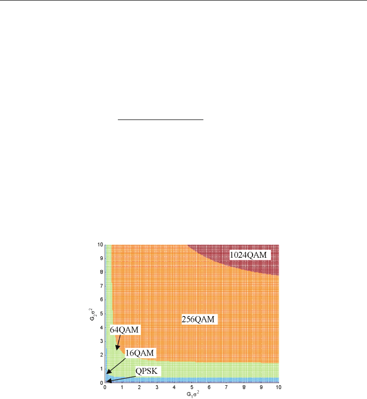
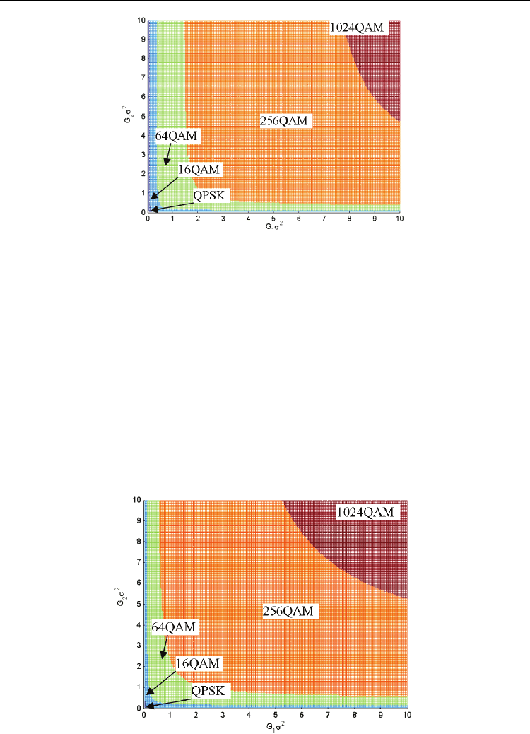
algorithm. With aid of computer simulation, we can obtain the (G
1
, G
2
) area to adopt the l-th
modulation, i.e. Φ
l
for all l. The areas of Φ
l
when P/σ
2
=30dB for Rayleigh fading channel are
depicted in Fig. 11, where different colour denotes (G
1
, G
2
) areas for different modulations.
Fig. 11. Area of Φ
l
for scheme with adaptive PA at SS
When P
1
is fixed and P
2
can be adjusted according to channel condition, we assume that
12
121212
(, )
,(,)
SS RS SS
GG
P
PPpGGdGdGPPP===−
∫∫
(41)
With the same method, we can obtain the (G
1
, G
2
) area to adopt the l-th modulation, i.e. Φ
l
for all l. The areas of Φ
l
when P/σ
2
=30dB for Rayleigh fading channel are depicted in Fig. 12.
B. Adaptive PA at SS and RS
When P
1
and P
2
can both be adjusted, we have to determine l, P
1
, and P
2
jointly. We assume
P
A
= P
1
+ P
2
, and follow the similar allocation to (27) to allocate power at SS and RS. In order
Advances in Greedy Algorithms
188
Fig. 12. Area of Φ
l
for scheme with adaptive PA at RS
to determine the (G
1
, G
2
) area for the l-th modulation, we consider another problem as
follows.
2
1 , (1,2,..., )
(, )
() ( , )
l
L
lij N
iGjG
bl pi G j G G
=∈
ΔΔ∈Φ
ΔΔΔ
∑∑
(42)
subject to
2
1 , (1,2,..., )
(, )
() ( , )
l
L
lij N
iGjG
bl pi G j G G
=∈
ΔΔ∈Φ
ΔΔΔ
∑∑
(38a)
With the same method above, we can obtain Φ
l
for all l in the case. The areas of Φ
l
when
P/σ
2
=30dB for Rayleigh fading channel are depicted in Fig. 13.
Fig. 13. Area of Φ
l
for scheme with adaptive PA at SS and RS
Greedy Algorithm: Exploring Potential of Link Adaptation Technique
in Wideband Wireless Communication Systems
189
From Fig. 11 to Fig. 13, we can see that the boundaries between the areas of Φ
l
are like
hyperbolas. The areas of Φ
l
for the scheme with adaptive PA at SS and the scheme with
adaptive PA at RS are reverse. As for the scheme with adaptive PA at SS and RS, the areas to
adopt higher order modulation (e.g. 1024QAM) are wider than the other two schemes. That
is to say, this scheme is more likely to adopt higher order modulation (allocated with more
bits), because both P
1
and P
2
can be adjusted and more adaptation can be obtained.
5.4 Simulation and analysis
In order to evaluate the performance of the proposed solutions in the section, numerical
simulation is carried out, in which both large-scale fading and small-scale fading are both
taken into consideration. The number of sub-carriers is 32. We assume
1, 1,
,
kkSR
HhD
η
−
=
and
2, 2,kkRD
HhD
η
−
=
, where h
1,k
and h
2,k
denote the small-scale fading, and they follow Rayleigh
distribution; D
SR
and D
RD
denote the distance between SS and RS, and distance between RS
and DS, respectively; D
SR
+ D
RD
=1. η denotes path loss exponent for large-scale fading,
which is 4 in the simulation; H
1,k
and H
2,k
are assumed to be available for SS and RS. For
reason of fairness, we assume P
SS
= P
RS
= P/2. For the following description, we define
SNR=P/σ
2
. The text in the legend is made short, e.g. “adaptive SS” is short for “adaptive PA
at SS”.
1) BER performance: First, we investigate BER performance of the proposed schemes in the
section. Fig. 14 gives out their BER performance vs. SNR for the schemes. When SNR is low,
low order modulation (e.g. QPSK) may be adopted frequently; when SNR is high, higher
order modulation (e.g. 256QAM) may be adopted, so BER remains almost the same as that
when SNR is low. It can be seen that all solutions can bring to BER performance close to the
target BER 10
-3
. This is because the power allocation at SS and RS can make the SNR of
received signals to be the threshold to satisfy BER
tgt.
Hence, the proposed schemes can
perform well in BER performance.
0 5 10 15 20 25 30
10
-4
10
-3
10
-2
SNR (dB)
BER
Adapt SS, IPC
Adapt RS, IPC
Adapt SS & RS, IPC
Adapt SS, APC
Adapt RS, APC
Adapt SS & RS, APC
Fig. 14. BER vs. SNR for the solutions when D
SR
=0.5
Advances in Greedy Algorithms
190
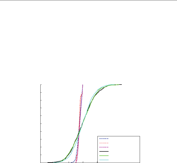
2) Transmit power constraint: Fig. 15 shows the cumulative distribution function (CDF) of
the normalized total power P
A
/P, where
1, 2,
1
1/ ( )
K
Akk
k
P
KPP
=
=+
∑
. As for the three schemes
with IPC, the distributions of P
A
are almost the same. The value of P
A
/P ranges from 0.92
to 1, which means that the instantaneous total power P
A
is always lower than P, which is
the requirement of IPC. As for the three schemes with APC, the distributions of P
A
are
almost the same, too. Hence, for the scheme of adaptive PA at SS and RS, though the
transmit power can both be adjusted at SS and RS, the range for the total power is not
improved, i.e. more adaptation on power doesn’t cause the total power to vary more.
From the figure, P
A
of the schemes with APC can range more widely than that with IPC,
from 0.75 to 1.25 approximately, but its mean value is restricted to be P. Compared with
the scheme with IPC, the scheme with APC can take use of more power in average.
0.7 0.8 0.9 1 1.1 1.2 1.3 1.4
0
0.1
0.2
0.3
0.4
0.5
0.6
0.7
0.8
0.9
1
P
A
/P
CDF
Adapt SS, IPC
Adapt RS, IPC
Adapt SS & RS, IPC
Adapt SS, APC
Adapt RS, APC
Adapt SS & RS, APC
Fig. 15. CDF of total power for the solutions when D
SR
=0.5 and SNR=20dB
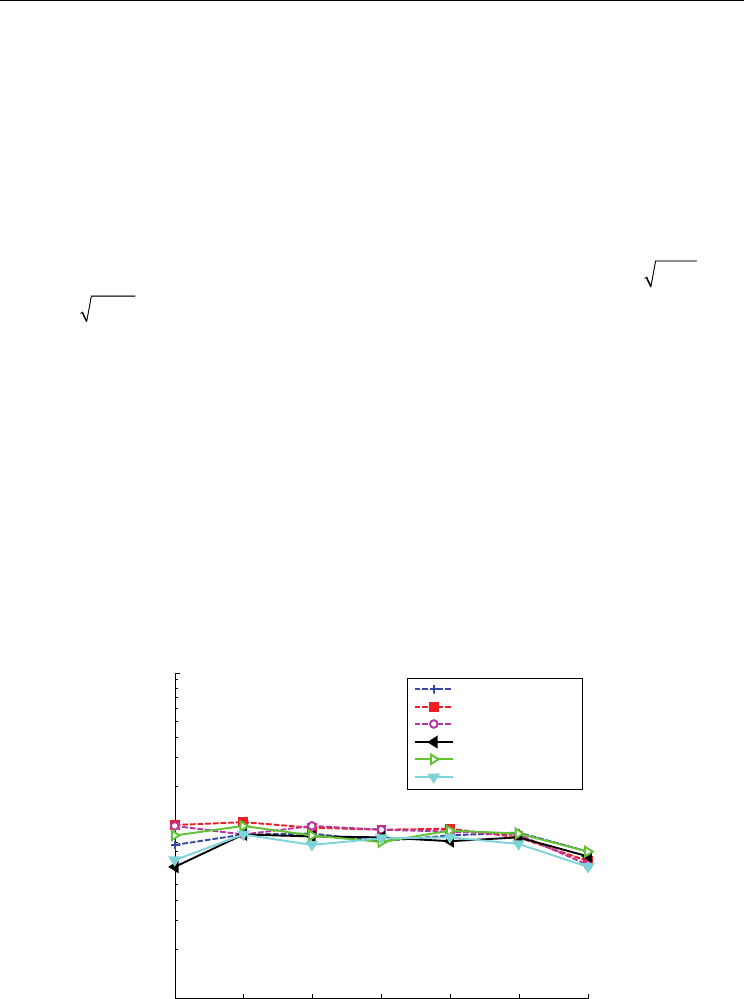
3) System throughput: Fig. 16 and Fig. 17 gives out the system throughput vs. DSR when
SNR equals to 0dB and 20dB, respectively. The throughput is calculated as the average
correctly transmitted bit number per OFDM symbol divided by the number of sub-carriers.
Throughput may be 0 because the channel condition is terrible and “no transmission” is
adopted. The schemes with IPC has lower throughput than that with APC, due to the fact
that they obtains different constraint for total transmit power. When SNR equals to 0dB, the
difference can achieve 10% (0.04bits/symbol). When SNR is higher, throughputs for IPC and
APC solutions are quite close, because the impact of transmit power constraint is not
dominant for throughput when SNR is high.
As a conclusion, the Greedy algorithm can be applied into OFDM relaying system to achieve
the maximum throughput subject to the BER and transmit power constraint.