Angermann L. (ed.). Numerical Simulations - Applications, Examples and Theory
Подождите немного. Документ загружается.

Laser Shock Peening: Modeling, Simulations, and Applications
341
The maximum strain in the loading direction across the surface is shown in Figure 7b. The
maximum value of -1.4×10
-2
was attained for the 5 ns pulse time using the BCJ model. A ≈
7% lower strain was predicted by the table format for each simulation pulse time. The
maximum strain attained by the 10, 50, and 100 ns cases was ≈ -1.2×10
-2
.
4.1.3 Residual stress
The predicted residual stresses were obtained from the surface element located at the center
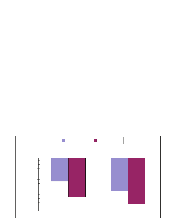
of the laser spot. A comparison of the measured and simulated residual stress values are
shown in Figure 8. Both the predicted and measured residual stresses are compressive, so
they agree with the nature and trend. There is some discrepancy between the two which
may be due to several factors that differentiate the experimental procedure from the
simulation. In addition to numerical errors, the first is the massive parallel LSP used for the
experiment which was not accounted for in the benchmark simulation. The overlaps of
consecutive laser peenings that occurred in LSP experiments would increase the magnitudes
of compressive residual stress. The predicted residual stresses from both single and two LSP
passes are expected to be lower than those from the experiments. The second is that the x-
ray diffraction technique using Cr
Kα
radiation actually measures an average residual stress
in the depth of x-ray penetration (5-10 μm). In addition, the exact location of residual stress
measurement with regard to the laser peened zone can not be accurately controlled for the
experiment. For the measurement itself, the residual stress magnitudes across the peened
surface are different just due to the nonuniform nature of surface integrity. Unless high
precision calibration and control can be carried out first, the x-ray and other non-destructive
measurement methods are only useful for comparative purpose.
-220
-310
-367
-434
-500
-400
-300
-200
-100
0
1 Pass 2 Pass
Residual Stress s11, MPa
Simulation Experiment
Fig. 8. Comparison of predicted surface residual stress s11 with measured data
4.2 Case 2: LSP simulation of fabricating micro dent arrays on titanium surface
A 3D finite element simulation model was developed to fabricate micro dent arrays on
titanium Ti-6Al-4V surfaces as shown in Figure 2, for improving tribology performance. Ti-
6Al-4V is a widely used engineering material in aerospace, automotive, and biomedical
Numerical Simulations - Applications, Examples and Theory
342
industries. Micro surface structures of the LSP processed Ti-6Al-4V components is critical
for product performance. However, the surface deformation and mechanical behavior in
patterning a Ti-6Al-4V surface has not been well understood. The simulation aims to
understand the laser/material interaction and the related mechanical phenomena. The
material constants (C
1
– C
20
) were determined by fitting the ISV model to the baseline test
data using a non-linear square fitting method. The fitted material constants are shown in
Table 2 (Guo et al., 2005). The modulus of elasticity for Ti-6Al-4V is 114 GPa. Poisson’s ratio
is 0.34 at room temperature. The density is 4430 kg/m
3
.
ISV
parameter
Material
constants
ISV
parameter
Material
constants
C1 (MPa) 1.0 C11 (s/MPa) 205
C2 (K) 0.2 C12 (K) 0
C3 (MPa) 1570 C13 (1/MPa) 1.9E-3
C4 (K) 10 C14 (K) 0
C5 (1/s) 1.0E-5 C15 (MPa) 619
C6 (K) 0 C16 (MPa/K) 3.8E-1
C7 (1/MPa) 7.0E-2 C17 (s/MPa) 5.0E-4
C8 (K) 0 C18 (K) 0
C9 (MPa) 1866 C19 1.0992E-3
C10 (MPa/K) 0.3 C20 (K) 876
Table 2. ISV material constants of Ti-6Al-4V
4.2.1 Simulated dent geometry
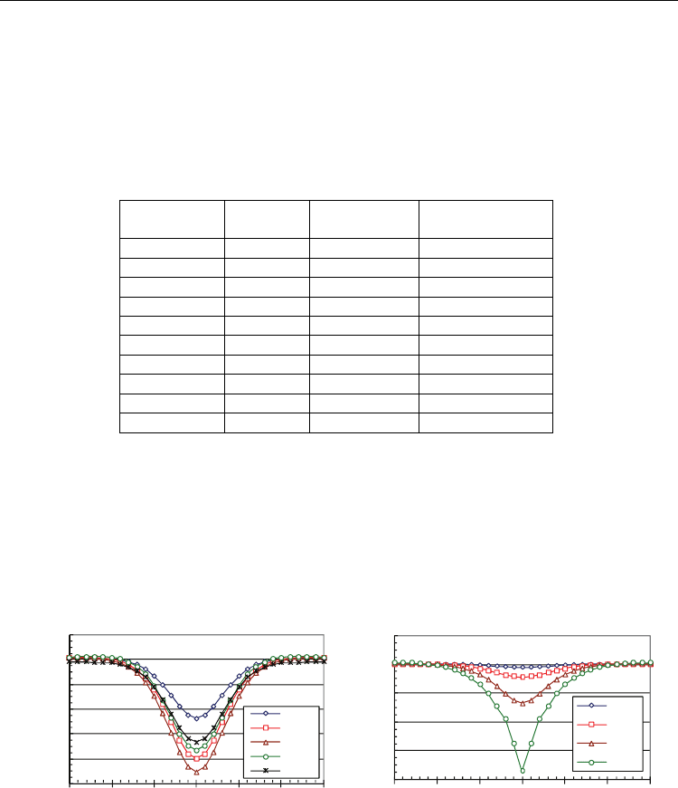
Figure 9a depicts the dent profiles for the various pulse times. Each dent was measured 50
ns after the simulation. Initially, increasing the pulse time leads to an increase in depth.
However, the 30 ns simulation has the maximum depth at 0.9 µm. The simulations with
pulse times greater than 30 ns exhibited a decrease in the depth. This suggests there is an
optimal pulse time which produces the deepest dents given a peak pressure.
-1.0
-0.8
-0.6
-0.4
-0.2
0.0
0.2
-15 -10 -5 0 5 10 15
Depth (microns)
Normalized radial position (microns)
7 ns
15 ns
30 ns
45 ns
60 ns
-8.0
-6.0
-4.0
-2.0
0.0
2.0
-15 -10 -5 0 5 10 15
Depth (microns)
Normalized radial position (microns)
3 GPa
4 GPa
5 GPa
6 GPa
(a) constant peak pressure of 4 GPa (b) constant pulse time of 30 ns
Fig. 9. Simulated dent profiles
Figure 9b shows the dent profiles as the peak pressure increases. There is a non-linear
relationship between the dent depth and peak pressure. As the load increases, the depth of the
dent increases as well. However, the radius of each dent is about 20 microns. A comparison
between the simulated dent contours and measured ones will be conducted in a future study.
Laser Shock Peening: Modeling, Simulations, and Applications
343
4.2.2 Surface material behavior at different peening time
Material behaviors at the surface are characterized by the stress/strain graphs along the
peening or depth direction (axis-3). Each stress/strain profile plotted represents the
maximum transient stress/strain during the peening process. The corresponding radial
curves are corresponding stress/strain graphs where the maximum occurs along the depth.
Transient stress profiles:
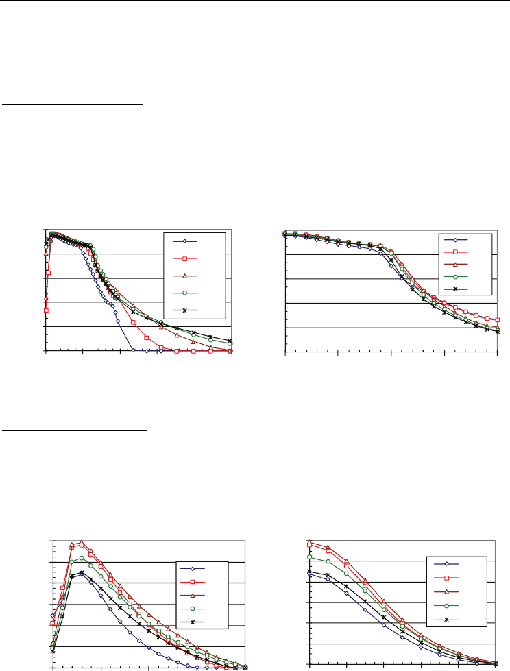
Von Mises stress along the depth is plotted in Figure 10a. In each
simulation, the maximum von Mises is 1.45 GPa and occurs about 3 µm below the surface
and gradually decreases to 1.27 GPa. The stress then sharply decreases toward zero as the
depth increases. Surface material at different peening times experiences similar von Mises
characteristics but at different depths. Figure 10b shows von Mises profile in the radial
direction 3 µm in the subsurface. In the radius of 9 µm, the von Mises stress remains greater
than 1.2 GPa. Then, the stress begins to decrease exponentially.
0
0.3
0.6
0.9
1.2
1.5
0 1530456075
von Mises (GPa)
Depth below surface (microns)
7ns
15ns
30ns
45ns
60ns
0
0.3
0.6
0.9
1.2
1.5
0 5 10 15 20
von Mises (GPa)
Radial position (microns)
7ns
15ns
30ns
45ns
60ns
Fig. 10. von Mises stress distributions at different peening time
Transient strain profiles:
The effective plastic strain PEEQ along the depth, Figure 11a,
exhibits an inverse relationship with the peening time. The plastic strain decreases with the
increased peening time. However, below the surface that is not the case. The 30 ns peening
time induces the maximum plastic strain. PEEQ converges to zero at 15 µm to 20 µm in
subsurface. Figure 11b illustrates the radial profiles of PEEQ which extends 10 µm in the
radial direction.
0
0.02
0.04
0.06
0.08
0.1
0.12
0 5 10 15 20
PEEQ
Depth below surface (microns)
7ns
15ns
30ns
45ns
60ns
0
0.02
0.04
0.06
0.08
0.1
0.12
0246810
PEEQ
Radial position (microns)
7ns
15ns
30ns
45ns
60ns
Fig. 11. Effective plastic strain distributions at different peening time
Numerical Simulations - Applications, Examples and Theory
344
Strain rate profiles: Figure 12a shows the strain rate along the depth for each peening time.
Material at the 7 ns peening case experiences the largest strain rate at 31×10
6
/s at 3 µm in
the subsurface. As peening time increases, the strain rate decreases non-linearly. In each
case, the peak rate occurs at 2 to 3 µm below the surface. Figure 12b shows the radial profiles
of the strain rate which extends approximately 10 µm from the peening center. The strain
rate for the 7 ns case converges more rapidly in the radial direction than other cases.
-35
-25
-15
-5
5
0 5 10 15 20 25 30
ER33 (E6/s)
Depth below surface (microns)
7ns
15ns
30ns
45ns
60ns
-35
-25
-15
-5
5
0 5 10 15 20
ER33 (E6/s)
Radial position (microns)
7ns
15ns
30ns
45ns
60ns
Fig. 12. Strain rate distributions at different peening time
4.2.3 Surface material behavior at different peening pressure
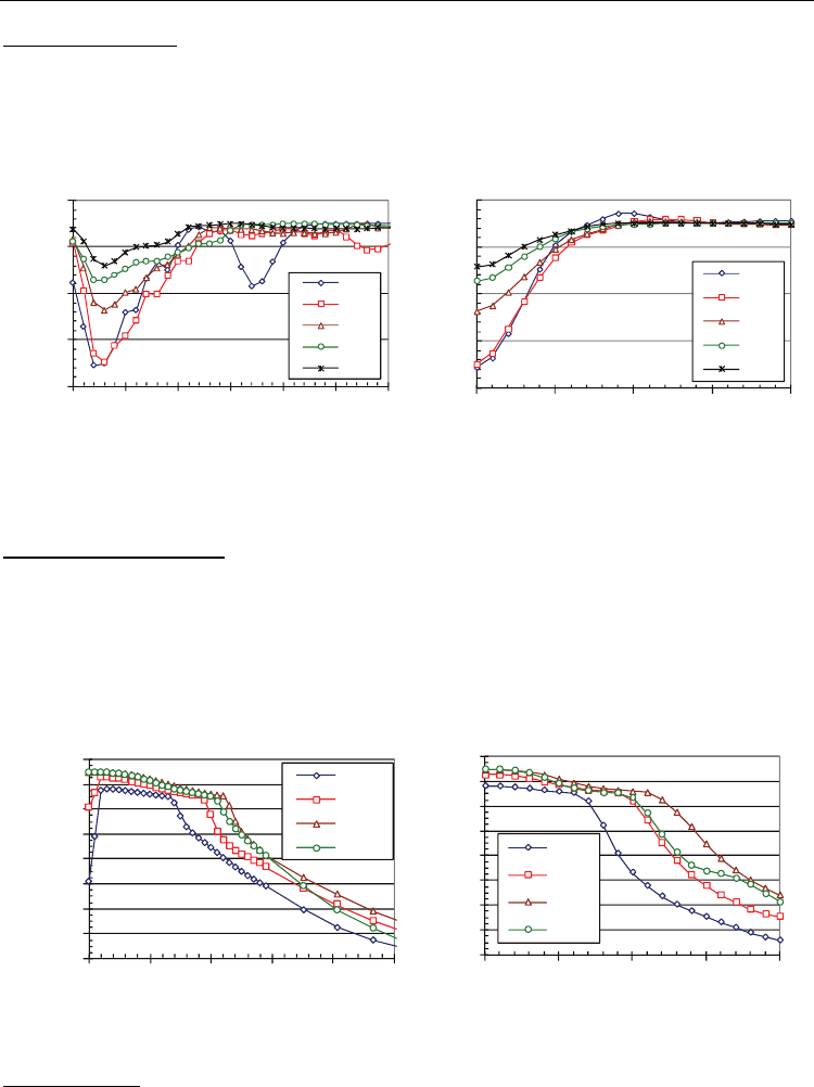
Transient stress profiles: Von Mises profiles in the depth are plotted in Figure 13a. At peak
pressures 3 GPa and 4 GPa, the maximum von Mises occurs at 3 µm in the subsurface. As
peak load increases the maximum von Mises moves toward the surface. It is also observed
that von Mises profiles overlap at peak pressures 5 GPa and 6 GPa. It implies that increasing
the peak pressure over 6 GPa will saturate von Mises stress. Initially, the stress gradually
decreases along the depth. Once it decreases to 1.3 GPa, it rapidly drops and converges
toward zero. Figure 13b shows the stress along the radial direction. It exhibits a similar
phenomenon seen in the depth direction.
0
0.2
0.4
0.6
0.8
1
1.2
1.4
1.6
0 1020304050
von Mises (GPa)
Depth below surface (microns)
3 GPa
4 GPa
5 GPa
6 GPa
0.0
0.2
0.4
0.6
0.8
1.0
1.2
1.4
1.6
0 5 10 15 20
von Mises (GPa)
Radial position (microns)
3 GPa
4 GPa
5 GPa
6 GPa
Fig. 13. von Mises stress distributions at different peening pressure
Strain profiles:
The equivalent plastic strain in the depth is plotted in Figure 14a. The
maximum plastic strain at 6 GPa peak pressure is on the surface, while it moves deeper into
the subsurface as the peak load decreases. For example, it moves to 3 µm deeper for the case of
3 GPa peak pressure. The corresponding radial profiles for PEEQ are shown in Figure 14b.
Laser Shock Peening: Modeling, Simulations, and Applications
345
0
0.4
0.8
1.2
1.6
2
0246810
PEEQ
Radial position (microns)
3 GPa
4 GPa
5 GPa
6 GPa
0
0.4
0.8
1.2
1.6
2
0 5 10 15 20
PEEQ
Depth below surface (microns)
3 GPa
4 GPa
5 GPa
6 GPa
Fig. 14. Effective plastic strain distributions at different peening pressure
Strain rate profiles:
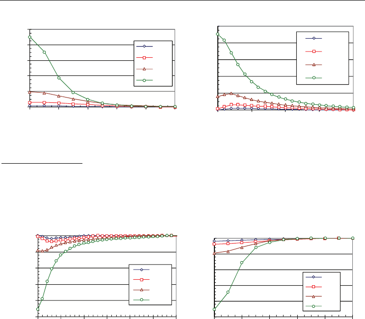
Figure 15a shows that the maximum strain rate is 226×10
6
/s on the
surface at 6 GPa peak pressure. As peak pressure decreases, the maximum strain rate moves
deeper below the surface. In addition, the simulations at peak pressures of 3 GPa and 4 GPa
experienced much smaller strain rates (< 2×10
6
) on the surface. But the maximum strain
rates occur at 3 µm in the subsurface. The corresponding radial profiles of the strain rate in
Figure 15b extend approximately 6 µm from the peening center.
-250
-200
-150
-100
-50
0
0 5 10 15 20 25 30
ER33 (E6/s)
Depth below surface (microns)
3 GPa
4 GPa
5 GPa
6 GPa
-250
-200
-150
-100
-50
0
0246810
ER33 (E6/s)
Radial position (microns)
3 GPa
4 GPa
5 GPa
6 GPa
Fig. 15. Strain rate distributions at different peening pressure
4.3 Case 3: LSP simulation of peening biomedical material for enhanced corrosion
performance
A 3D semi-infinite model was used to simulate micro scale laser shock peening of
biodegradable Mg-Ca. The material constants (C
1
– C
20
) of the biomaterial were determined
by fitting the ISV model to the baseline test data using a non-linear square fitting method
(Guo et al., 2005). The fitted material constants are shown in Table 3 (Guo & Salahshoor,
2010). The modulus of elasticity for Mg-Ca is 45 GPa. Poisson’s ratio is 0.33 at room
temperature. The density is 1750 kg/m
3
.
A series of four simulations were performed in order to simulate sequential LSP. The Mg-Ca
surface was peened once per simulation. Each simulation is composed of two steps. In the
first step, the shock pressure is applied on the top surface. Next, the stresses and strains are
allowed sufficient time to relax so that the solution has time to stabilize. The results from the
first simulation were imported to the second simulation and so on until the surface was
peened 4 times.
Numerical Simulations - Applications, Examples and Theory
346
ISV
parameter
Material
constants
ISV
parameter
Material
constants
C
1
(MPa) 1.0 C
11
(s/MPa) 1E-4
C
2
(K) 600 C
12
(K) 0
C
3
(MPa) 850 C
13
(1/MPa) 0.7
C
4
(K) 20 C
14
(K) 100
C
5
(1/s) 1.0E-7 C
15
(MPa) 3E4
C
6
(K) 0 C
16
(MPa/K) 39
C
7
(1/MPa) 0.1 C
17
(s/MPa) 380
C
8
(K) -300 C
18
(K) -900
C
9
(MPa) 2500 C
19
0.2
C
10
(MPa/K) 0 C
20
(K) 312.8
Table 3. ISV material constants of Mg-Ca alloy
4.3.1 Simulation scheme
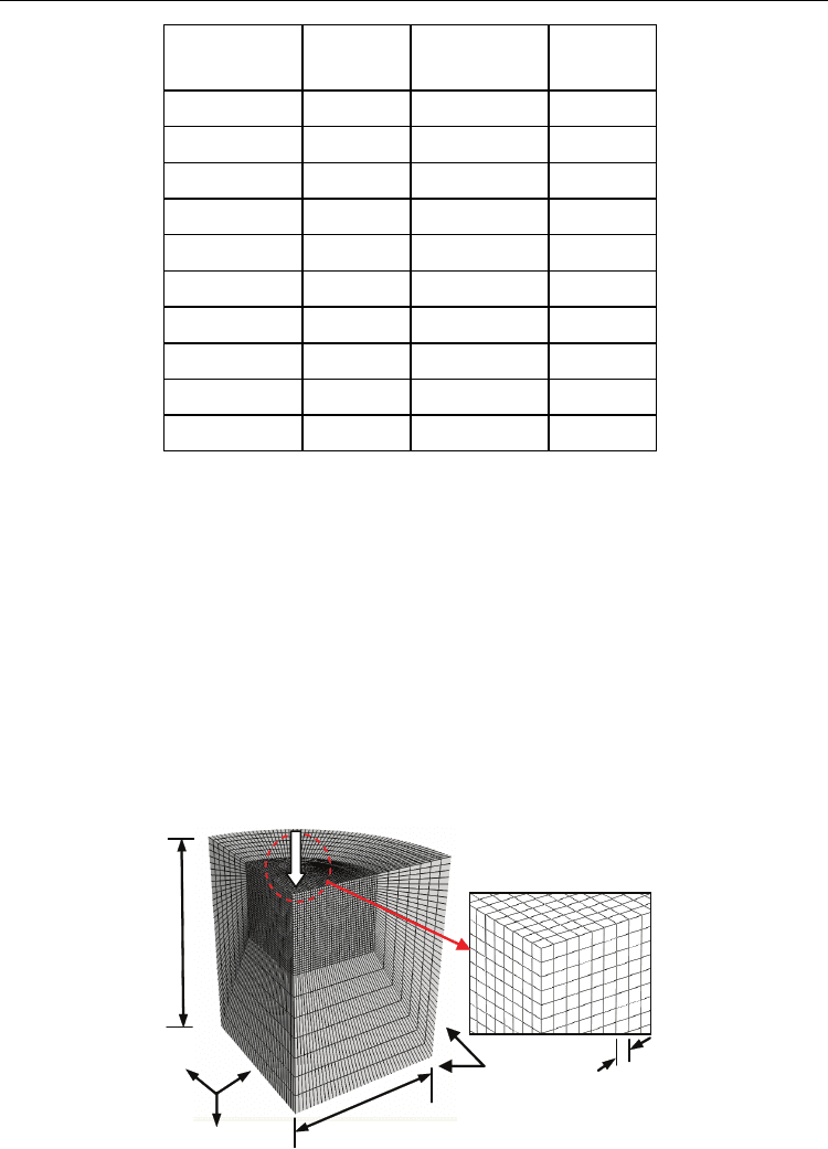
The 3D model in Figure 16 contains a quarter cylinder of 70,818 C3D8R finite elements and
3,575 CIN3D8 infinite elements. The quarter cylinder mesh allows for a comprehensive
analysis of the three dimensional stress and strain behavior below the surface while
minimizing the computation time. Infinite elements as quiet boundary along the back and
bottom surfaces were implemented to allow for stress waves to pass through a non-
reflective boundary.
The mesh has two regions with different mesh densities. As expected, the area where the
pressure is applied contains a higher mesh density than the outer regions of the model. The
dense mesh region consists of 30 µm wide cubic elements. Micron level elements provide a
suitable spatial resolution of the output variables to ensure spatial convergence.
Infinite Elements
2400 μm 3
1
2
Peening direcon
30 μm
3000 μm
Fig. 16. Three-dimensional FEA simulation of LSP
Laser Shock Peening: Modeling, Simulations, and Applications
347
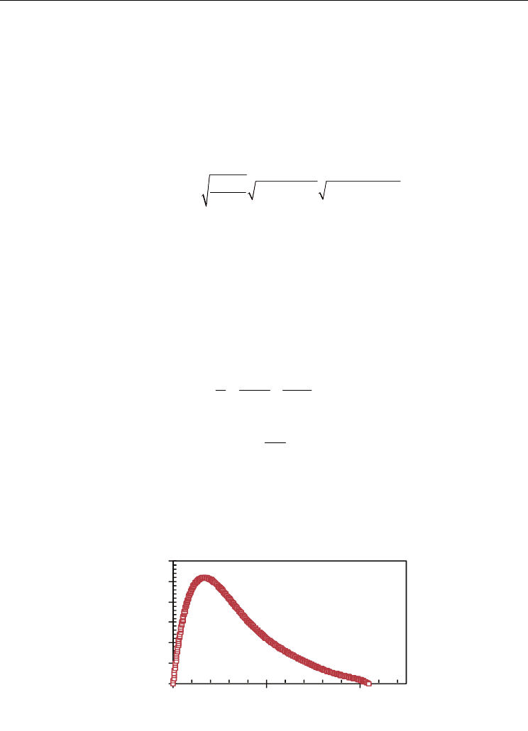
The pressure induced by LSP is a function of elapsed time and radial position. A useful
approximation for P(t) is to assume it follows a 6
th
order polynomial as shown in Figure 17.
The generic profile is based on numerous researchers (Berthe et al., 1997; Fabbro et al., 1990;
Devaux et al., 1993; Wu & Shin, 2005; Zhang et al., 2004) who have measured the P(t) as a
function of time. The critical components of P(t) are the pulse time and the peak pressure.
The pressure pulse time typically last 2-3 times longer than the laser pulse (Devaux et al.,
1993; Berthe et al., 1999; Zhang & Yao, 2002). For the purpose of these simulations, the
pressure pulse was assumed to be 3 times longer than the 7 ns laser pulse. The peak
pressure for P(t) in water confined regime was estimated by
22
( ) 0.01 ( / ) ( / )
23
o
PGPa Zg cms I GW cm
α
α
=
+
(17)
where P is the peak pressure, Z is combined shock impedance defined by the following Eq.
(18), I
o
is the power density given by Eq. (19), and α is a correction factor for the efficiency of
the interaction (Fabbro et al., 1990; Peyre et al., 1996). Since the ablative material used in
these experiments was relatively thick and absorbent compared to other materials used in
literature, α was estimated to be low (0.1) such that the majority of the energy was absorbed
by the ablative material. Z
MgCa
is defined as the product of the density and shock velocity
(Z
MgCa
=ρ
MgCa
U
MgCa
). The density of Mg-Ca is 1750 kg/m
3
and the shock velocity is
approximated based on the wave speed of sound through Mg-Ca (≈ 5000 m/s). Z
MgCa
and
Z
water
are 8.75x10
5
and 1.65x10
5
g/cm
2
, respectively.
21 1
Mg
Ca water
ZZ Z
=+ (18)
o
P
E
I
tA
= (19)
where E is the average energy per pulse given as 0.2667 J. t
p
is the simulated pressure pulse
time (21ns). A is the cross-sectional area of the generated plasma. The diameter of the
pressure wave is approximately 250 µm which results in a peak pressure of 5 GPa.
0
1
2
3
4
5
6
01020
Applied Pressure, P(t)
(GPa)
Time (ns)
Fig. 17. Spatially uniform shock pressure, P(t)
Numerical Simulations - Applications, Examples and Theory
348
In this study, the radial expansion of plasma was taken into account for the following
reasons. First, the experimental laser spot size is on the order of 100 microns. With such a
small spot size, the expansion of plasma may not be neglected in the radial direction.
Furthermore, the experimental ablative layer is not fully vaporized because it is thick and
absorbs energy well. As a consequence, the pressure wave generated by the plasma has time
and space to expand in all directions before entering the metal substrate. Radial expansion
of plasma was modeled by allowing the applied pressure to act perpendicular to the
deformed surface. Initially the pressure is one dimensional. As deformation occurs, the
pressure follows the deformed surface resulting in a spherical shape pressure that expands
in the radial direction.
Implementing the temporal and spatial shock pressure is very challenging and a user load
subroutine is therefore required. The user subroutine VDLOAD (Warren et al., 2008) of
shock pressure has been programmed to apply a non-uniform shock pressure across the top
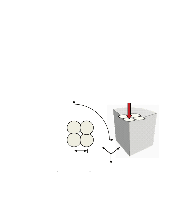
surface. The circular pressure was applied in four locations. Figure 18 shows the peening
distribution along the top surface. The spacing between simulated peens is 800 µm.
1
2
1
st
2
nd
3
rd
4
t
h
800 μm
3
1
2
Fig. 18. Sequence of peening simulations (quarter shown)
4.3.2 Simulation results
Material behavior is characterized by stress/strain graphs along the peening or depth
direction (axis-3 in Figure 18) and radial directions (axis-1&2). Each stress/strain profile
represents the stabilized residual stress/strain. Residual stress/strain was achieved 30 µs
after the pressure pulse.
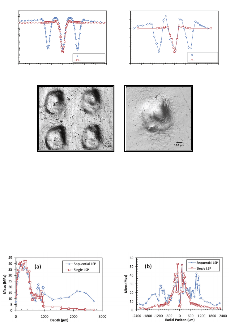
Dent geometry: Figure 19a depicts the simulated dent profiles for sequential and single LSP.
The diameter of the simulated dents was 600-700 µm and had a depth of 10 µm. There was a
negligible effect of neighboring dents on the overall dent depth. However, it was observed
that neighboring dents do influence the tensile pile up region. The magnitude of the pile up
increased approximately 50%. It is believed to be due to the radial expansion of neighboring
peens. Tensile pile up is critical to tribological applications such as implants. A tensile
region on the surface can drastically affect the wear and fatigue performance of a surface.
Figure 19b shows the experimental dent profiles for sequential and single LSP. The
experimental dents also had a diameter between 600-700 µm and a depth of 11µm. Results
from the experiments confirms the validity of the simulation. Figure 19c and 19d are optical
images of dents by sequential and single LSP.
Laser Shock Peening: Modeling, Simulations, and Applications
349
-14
-12
-10
-8
-6
-4
-2
0
2
4
-2400 -1800 -1200 -600 0 600 1200 1800 2400
Depth (µm)
Radial Position (µm)
Sequential LSP
Single LSP
-16
-12
-8
-4
0
4
8
-2400 -1800 -1200 -600 0 600 1200 1800 2400
Depth (µm)
Radial Position (µm)
Sequential LSP
Single LSP
(a) Simulated dent profile (b) Experimental dent profile
(c) Sequential LSP (d) Single LSP
Fig. 19. Simulated and measured dent topography
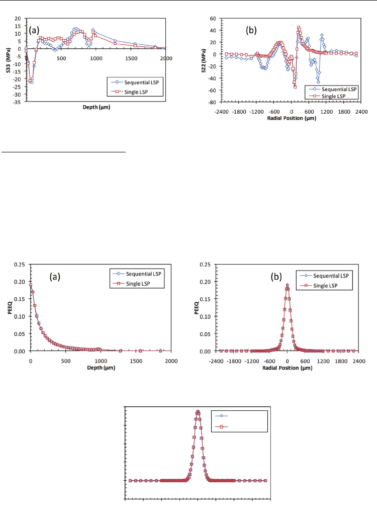
Residual stress profiles: The predicted residual von Mises stress and S33 stress along the
depth direction are shown in Figures 20a and 21a. The von Mises stress penetrated deeper
into the surface for sequential peening. As expected, sequential peening had a greater effect
on the surface residual stress since a larger area was exposed to peening. Along the depth
direction, the residual stress S33 is compressive for approximately 150 µm. The compressed
region is followed by a tensile region that eventually approaches 0 MPa. The magnitude of
the compressive residual stress below the surface is 23 MPa. The predicted residual von
Mises stress and S22 stress along the radial direction are shown in Figures 20b and 21b.
Single peening neglects the effects from neighboring stress fields on the surface residual
stress. Future work will include comparing simulated residual stress profiles to
experimental residual stress.
Fig. 20. Residual von Mises stress along depth (a) and radial (b) directions
Numerical Simulations - Applications, Examples and Theory
350
Fig. 21. Residual stress, S33 along depth (a) and S22 along the radial (b) directions
Strain and strain rate profiles: The plastic strain in the depth and radial directions is shown
in Figure 22. The plastic strain extended 500 µm below the surface. The residual stress from
previous peens had a negligible effect on the plastic strain. The maximum plastic strain
occurred on the top surface and in the center of the dent. The diameter of the plastic zone is
directly related to the topography of the dent. The peak strain rate in peening direction for
the simulations was 19 × 10
6
s
-1
in Figure 23.
This work focuses on the experiment and FEA simulation of LSP MgCa alloy. More
experimental results are needed to verify the simulation results. Further work is needed to
demonstrate the effectiveness of the resulting surface by this method in improving surgery
of bone ailments.
Fig. 22. Equivalent plastic strain PEEQ along depth (a) and radial (b) directions
-5.0E+06
0.0E+00
5.0E+06
1.0E+07
1.5E+07
2.0E+07
-2400 -1800 -1200 -600 0 600 1200 1800 2400
ER33 (s
-1
)
Radial Positon (µm)
Sequential LSP
Single LSP
Fig. 23. Strain rate on the top surface, ER33
