AckermannTh. (ed) Wind Power in Power Systems
Подождите немного. Документ загружается.


//INTEGRAS/KCG/P AGIN ATION/ WILEY /WPS /FINALS_1 4-12- 04/0470855088_ 23_CHA22 .3D – 481 – [479–504/26]
17.12.2004 10:46PM
Kingdom and Sweden. Also, in the USA the first offshore wind energy projects are
currently being discus sed (e.g. off Cape Cod and Long Island).
Future projects not only will include wind turbines with a higher rated capacity
( 3 MW) but also will be significantly larger in total size and further away from the shore,
hence most likely also to be in deeper waters, of up to 40 m. Typical future project proposals
for offshore wind farms are in the range of 250–1000 MW. This will require new concepts
for the overall transmission system, including concepts for transmission within the offshore
wind farm as well as to shore and for network integration into the onshore power system.
This chapter will focus mainly on the different options for the transmission system
between a large ( 100 MW) offsho re wind farm and the onshore power network.
22.2 General Electrical Aspects
The internal electric system of an offshore wind farm and its connection to the main
power syst em pose new challenges. Onshore, the standard solution is an AC network
within the wind farm, which collects the power production of each wind turbine. The
voltage level within a wind farm is usually the same as the medium voltage level of the
distribution network point. As most wind turbine generators operate at a generator
voltage level of 690 V, transformers that are installed directly in or close to the basement
of each wind turbine are used to increase the generator voltage level to the voltage level
in the wind farm network. The highest medium voltage level used within an onshore
wind farm lies usually in the range of 33–36 kV, as the market offers competitive
standardised equipment for this voltage range.
However, offshore wind farms tend to be bigger, and the distance between wind turbines
is usually greater than that in onshore wind farms because of the larger wake effect
offshore. Often, the distance to the shore or to the next (offshore) transformer station is
also significantly longer than for onshore wind farms. For large offshore wind farms with
an AC network, higher voltage levels will certainly be useful in order to minimise power
losses, but higher voltage levels may result in bigger transformers and higher costs for these
transformers. The transformers will be placed in the nacelle, the tower or in a container
next to the wind turbine; hence the size of the transformer might become an issue. In
addition, the cost and size of switchgears will also increase with voltage levels. Today, a
collection voltage of up to 36 kV is considered the standard solution. Research by
Lundberg (2003), however, indicates that for a small offshore wind farm (around
60 MW) that uses Type C turb ines and has a maximum distan ce to shore of 80 km the most
cost-effective voltage level is 45 kV.
(1)
In the future, there may be other more cost-effective
solutions, once wind turbine manufacturers start to offer wind turbines with generator
voltage levels higher than 690 V (e.g. 4000 V or more). Higher voltage levels, however, will
require better trained mainten ance staff and enhanced safety, w hich will increase costs.
Existing smaller offshore wind farms that are reasonably close to the shore have opted
for a comparatively low voltage level. The reason is that the reduction in (load) losses is
not sufficient to justify the additional costs for the equipment required for higher
(1)
For definitions of Type A to D wind turbines, see Section 4.2.3.
Wind Power in Power Systems 481

//INTEGRAS/KCG/P AGIN ATION/ WILEY /WPS /FINALS_1 4-12- 04/0470855088_ 23_CHA22 .3D – 482 – [479–504/26]
17.12.2004 10:46PM
voltage levels. The same applies to smaller offshore wind farms that are currently being
planned. The seven turbines of the Swedish Utgrunden offshore wind farm (9.975 MW),
for instance, are interconnected at a voltage level of 20 kV. The cable to shore has a
length of 8 km and is operated at 20 kV. Onshore, the voltage is raised to 50 kV.
For the Danish Middelgrunden offshore wind farm, which is somewhat larger, at
40 MW, a voltage level of 30 kV was chosen for the connection between the 20 turbines
and the approximately 3 km long cable to shore (Middelgrunden, 2004). The Danish
Horns Rev wind farm, which was constructed during 2002, has a capacity of 160 MW
and uses a voltage level of 36 kV within the wind farm. Horns Rev is the first offshore
wind farm that uses an offshore transformer platform. At the offshore transformer
station, the voltage level is raised to 150 kV to feed the approximately 15 km long AC
cable to shore (Horns Rev, 2004). The Danish Nysted offshore wind farm, with a
capacity of 165.6 MW, uses 33 kV as the collection voltage. It also includes an offshore
transformer station where the voltage is raised to 132 kV for the approximately 10 km
AC connection to shore (Steen Beck, 2002).
The network design of an offshore wind farm does not necessarily correspond to the
most energy-efficient ne twork layout (i.e. with lowest losses). The reason is that offshore
transformer stations are rather complex and include large support structures. Hence,
offshore transformer stations are very expensive and there is hardly any experience yet
regarding the reliability of offshore transformer stations.
22.2.1 Offshore substations
The Horns Rev offshore substation is designed as a tripod construction, in contrast to
the Nysted substation, which is based on a monopile construction. The Horns Rev
substation includes a steel building with a surface area of approxim ately 20 28 m
which is placed about 14 m above mean sea level. The platform accommodates, among
others things, the following technical installations (Horns Rev, 2004):
.
36 kV switch gear;
.
36/150 kV transformer;
.
150 kV switch gear;
.
a control and instrumentation system, as well as a communication unit;
.
an emergency diesel generator, including 2 50 tonnes of fuel;
.
sea-water-based fire-extinguishing equipment;
.
staff and service facilities;
.
a helipad;
.
a crawler crane;
.
an MOB (man overboard) boat.
The Horns Rev and Nysted offshore substations are unique. Nothing of this kind had
been built in the world before, not even for the offshore gas and oil industry, which
usually only operates at voltage levels of 13.8 kV. The two existing offshore substations
will provide important information about the reliability of offshore substations for
future projects.
482 Transmission Systems for Offshore Wind Farms
//INTEGRAS/KCG/P AGIN ATION/ WILEY /WPS /FINALS_1 4-12- 04/0470855088_ 23_CHA22 .3D – 483 – [479–504/26]
17.12.2004 10:46PM
However, offshore project developers are likely to adopt the simplest approach
possible, which might be also the most economic rather than the most energy-efficient
solution. They tend to avoid the installation of offshore transformer platforms whenever
possible. The planned 100 MW NoordZeeWind project in the Netherlands, for instance, will
not include an offshore substation. The internal voltage level of the wind farm and of the
8 km connection to shore will most likely b e 33 kV or 36 kV.
Very large wind farms ( 250 MW) that are located far off the shore may require a
number of offshore substations. The first step will be to connect each wind farm module
with a maximum capacity of 250 MW to a substation where the voltage is stepped up
[or converted to high-voltage direct current (HVDC)] for the transmis sion link to shore.
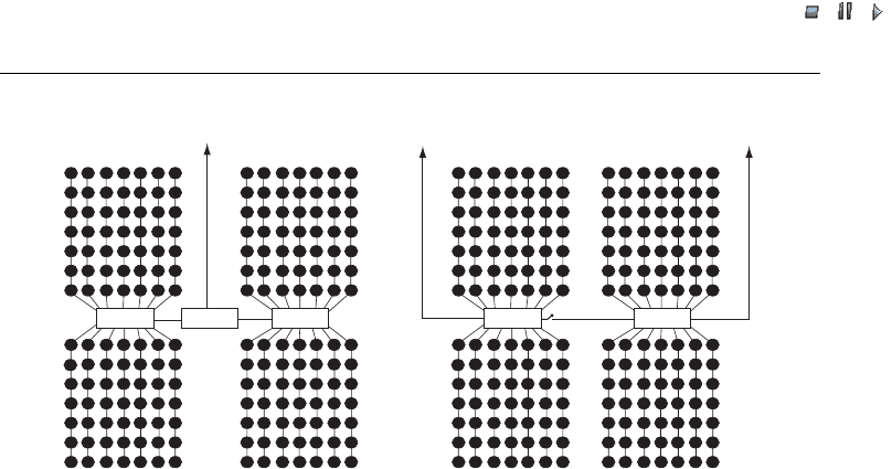
Another option is to connect each substation to shore (see also Figure 22.1) .
Large offshore wind farms can certainly have different layout configurations. Look-
ing at Figure 22.1, for instance, in Alternative B it might be possible to increase the
voltage level within each wind farm block and to have only one offshore substation per
block. This might reduce total investment costs yet increase the risk that the whole wind
farm may be lost in the case where there are technical problems with the single network
connection. Hence, designers of general wind farm layout have to consider not only the
main wind direction but also the technical transmission solution, the investment and
operating costs and the overall reliability as well as issues related to the location, such as
water depth throughout the proposed area (for a more detailed discussion of possible
layouts for offshore wind farms, see Lundberg, 2003; Martander, 2002).
22.2.2 Redundancy
Most electric networks of offshore wind farms that are currently under discussion have
no or very little redundancy. The turbines of a wind farm may be connected to a ‘radial’
network, as for example in Horns Rev. A radial network de sign means that a number of
OSS2OSS3
To shore
OSS1
Alternative B
OSS2OSS1
Alternative A
To shore To shore
Figure 22.1 Possible layouts for a 980 MW (196 5 MW) offshore wind farm. Note: OSS ¼
offshore substation
Wind Power in Power Systems 483

//INTEGRAS/KCG/P AGIN ATION/ WILEY /WPS /FINALS_1 4-12- 04/0470855088_ 23_CHA22 .3D – 484 – [479–504/26]
17.12.2004 10:46PM
turbines are connected to one feeder. The maximum number of turbines on each feeder
is determined by the maximum rating of the cable (Brakelmann, 2003). If the cable is
damaged the whole feeder will be disconnected until the fault is repaired. Redundancy
might be achieved by enabling connections be tween feeders. The last wind turbine in one
feeder could be connected to the last turbine in the next feeder, for instance. During
normal operation, this connection would be open. If there is a fault in one of these two
feeders, the connection would be closed.
For this, additional equipment would be required to isolate the fault. The goal is that
as many wind turbines as possible remain connected to the grid. It has also to be taken
into account that the number of wind turbines that may be connected to one feeder will
be lower, as the maximum cable rating must be able to cop e with twice as many turbines
in case the fault is close to the first turbine within one feeder. Today, the likelihood of a
fault and the associated costs are assumed to be lower than the costs for the additional
equipment – therefore, redundancy is not taken into consideration. In order to reduce
the likelihood of damage, the cables are usually buried 1–2 m into the seabed to protect
them from ships’ anchors and strong sea currents.
Usually, the cable from the offshore wind farm to the shore does not include any
redundancy either (see also Figure 22.1, Alternative A). A fault on this cable, however,
will result in a loss that is equivalent to the entire wind farm. The economic consequences
from such a fault may be huge. The repair might take months, depending on the
availability and current position of cable repair ships. It is, however, very difficult to
protect the cable from damage, particularly if the cable crosses major shipping routes. At
the First International Workshop on Transmission Networks for Offshore Wind Farms in
Stockholm, Sweden, it was reported that the anchors of large ships could dig down up to
13 m into the seabed. It is not practically viable to bury a cable at such a depth.
Redundancy could be achieved by using another, backup, cable following another route
to shore (see Figure 22.1, Alternative B). Besides the significant costs of such a second
connection to shore, it might be also very difficult to carry this out in practice. At many
locations, environmental restrictions would make it very difficult to find a second cabling
route. A second connection point to the onshore network might not always be available
either. Currently, no developers of offshore wind farms seriously consider any redundancy
for the onshore cabling. Experience from the operation of the first large offshore wind farms
will show whether redundancy for onshore connections will become necessary in future.
22.3 Transmission System to Shore
For the cabling to shore, either high-voltage alternating-current (HVAC) or high-
voltage direct-current (HVDC) connections could be used. For HVDC connections,
there are two technical options: line commutated converter (LCC) based HVDC and
voltage source co nverter (VSC) based HVDC technology.
All offshore wind farms that are currently operating (as of December 2003) have
adopted an AC alternative, and all those planned to be inst alled within the near future
(1–2 years) will also use an AC solution. This is because of the comparative ly small size
and/or the short distance between the shore and the existing wind farms. As the size of
future wind farms and the distance to shore is likely to increase, this might change.
484 Transmission Systems for Offshore Wind Farms
//INTEGRAS/KCG/P AGIN ATION/ WILEY /WPS /FINALS_1 4-12- 04/0470855088_ 23_CHA22 .3D – 485 – [479–504/26]
17.12.2004 10:46PM
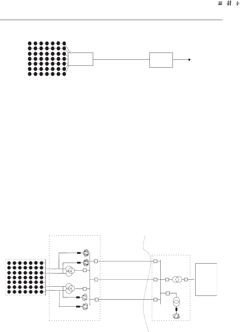
In the following, three different options for the connection of offshore wind farms to
shore are discussed in more detail. [The general layout of an offshore wi nd farm, which
may relate to either HVAC or HVDC transmission, is shown in Figure 22.2.]
22.3.1 High-voltage alternating-current transmission
An HVAC transmission system consists of the following main components: an AC
based collector system within the wind farm; perhaps an offshore transformer station
including offshore reactive power compensation; three-core polyethylene insulation
(XLPE) HVAC cable(s) to shore, and , onshore, possibly a stat ic VAR compensator
(SVC; Eriksson et al., 2003, Ha
¨
usler and Owman, 2002; see also Figure 22.3).
TheHVACsolutionwasimplementedattheHornsRev160MWwindfarminDenmark.
As this wind farm is only 21 km offshore, no compensation was needed at the offshore
transformer station. The cable used was a 170 kV three core XLPE cable with 630 mm
2
copper conductor.
Collecting
point
Grid
interface
PCC
Transmisson solution
Wind farm
Figure 22.2 Schematic layout of an offshore wind farm; the collecting point can be an offshore
substation. Note: PCC ¼ point of common coupling
300 MVA
300 MVA
SVC
SVC
30 kV
30 kV
30 kV
30 kV
600 MVA
150 kV
150 kV
400 kV
Offshore wind farm
Offshore substation
Shore Line
Onshore
network
150 kV, XLPE cable
Rating 200 MW
150 kV, XLPE cable
Rating 200 MW
150 kV, XLPE cable
Rating 200 MW
Onshore
substation
Figure 22.3 The basic configuration of a 600 MW wind farm with a high-voltage alternating-current
(HVAC) solution. Note:SVC¼ static VAR compensator; XLPE ¼ polyethylene insulation
Sources: based on Eriksson et al., 2003; Ha
¨
usler and Owman, 2002.
Wind Power in Power Systems 485

//INTEGRAS/KCG/P AGIN ATION/ WILEY /WPS /FINALS_1 4-12- 04/0470855088_ 23_CHA22 .3D – 486 – [479–504/26]
17.12.2004 10:46PM
With an increasing distance to shore, reactive power compensation will be required at
both ends of the cable (i.e. at the offshore substation, too). A 400 MW offshore wind farm
with two 150 kV, 120 km, cable systems, for instance, will require 150 MVAR compensa-
tion offshore as well as onshore (Eriksson et al., 2003). Furthermore, the maximum rating
of AC cables is currently limited to about 200 MW per three-phase cable, based on a
voltage rating of 150–170 kV, compensation at both ends of the cable and a maximum
cable length of 200 km. That means that a 1000 MW wind farm would need five cables for
the connection to shore, and that does not even take possible requirements for redundancy
into account.
For shorter distances, higher voltage ratings of up to 245 kV might be possible, which
would increase the maximum rating to 350–400 MW (Rudolfsen, 2001; Rudolfsen,
2002). A three-core, 1000 mm
2
, conductor cable operated at a system voltage of
230 kV with a maximum of 10 % voltage variation between no load and full load
can, for instance, transmit 350 MW over 100 km with losses of 4.3 %, or 300 MW over
200 km with losses of 7.3 % , if the cable is compensated equally at both ends (Rudolfsen,
2001). Higher voltage levels of up to 400 kV are under development, which may allow a
maximum transmission of 1200 MVA over a maximum distance of 100 km. It is, how-
ever, uncertain when such solutions will become commercially avail able.
Finally, the main disadvantage of HVAC solutions must be mentioned : with increas-
ing wind farm size and distance to shore, load losses will increase significantly. Also, an
increase in the transmission voltage level will lead to larger and more expensive equip-
ment (e.g. transformers) as well as more expensive submarine cables. Hence, an increase
in the voltage level is often only justifiable if an increase in capacity is required.
(2)
22.3.2 Line-commutated converter based high-voltage direct-current
transmission
The advantage of LCC based HVDC connections is certainly their proven track record.
The first commercial LCC HVDC link was installed in 1954 between the island of
Gotland and the Swedi sh mainland. The link was 96 km long, 20 MW rated and used
a 100 kV submarine cable. Since then, LCC based HVDC technology has be en installed
in many locations in the world, primarily for bulk power transmission over long
geographical distances and for interconnecting power systems, such as for the different
island systems in Japan and New Zealand (Hammons et al., 2000). Other well-known
examples for conventional HVDC technology are:
.
the 1354 km Pacific Interie DC link, with a rating of 3100 MW at a DC voltage of
500 kV;
.
the Itaipu link between Brazil and Paraguay, rated at 6300 MW at a DC voltage of
600 kV (two bipoles of 3150 MW).
(2)
The capacity charging current of long HVAC cable increases linearly with the voltage level as well as linearly
with the lengths of the cable. Hence, for a given wind farm capacity (e.g. 200 MW) the losses related to the
capacity charging current will be higher for a 245 kV solution than for a 150 kV system design.
486 Transmission Systems for Offshore Wind Farms
//INTEGRAS/KCG/P AGIN ATION/ WILEY /WPS /FINALS_1 4-12- 04/0470855088_ 23_CHA22 .3D – 487 – [479–504/26]
17.12.2004 10:46PM
However, there is no exp erience regarding LCC based HVDC offshore substations or
onshore in combination with wind power.
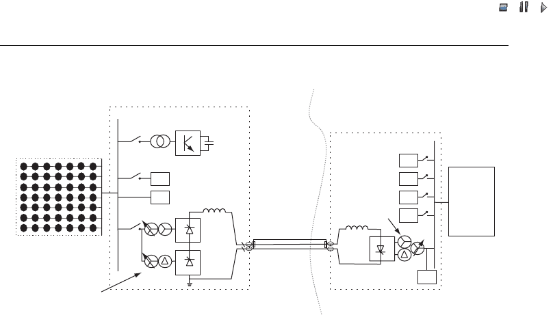
A thyristor based LCC HVDC transmission system consists of the following main
components: an AC based collector system within the wind farm; an offs hore substation
with two three-phase two-winding converter transformers as well as filters and either a
Statcom or a diesel generator that supply the necessary short-circuit capacity; DC
cable(s); and an onshore converter station with a single-phase three-winding converter
transformer as well as the relevant filters (Cartwright, Xu and Saase, 2004; Kirby et al.,
2002; see also Figure 22.4).
This technology requires comparatively large converter stations both on- and off-
shore, as well as auxiliary service at the offshore converter station. The auxiliary service
has to keep up a rather strong AC system at the offshore converter in order to enable the
operation of the line-commutated converters even during periods with no or very little
wind. This auxiliary offshore service will be most likely supplied by diesel generator(s)
(Kirby et al., 2002). Another solution, also referred to as hybrid HVDC , comprises a
LCC based HVDC converter and a Statcom, see Cartwright et al., 2004. The Statcom
provides the necessary commutation voltage to the HVDC converter and reactive power
compensation to the offshore network during steady state, dynamic and transient conditions.
The total conversion efficiency from AC to DC and back to AC using the two
converters (offshore and onshore) lies in the range of 97–98 % and depends on the
design details of the converter stations. A system design with 98 % efficiency will have
higher investment costs compared with a design with lower efficiency. Hence, the
advantage of an LCC HVDC solution are comparatively low losses (i.e. 2–3 % for a
145 kV, 50 Hz
380 kV
Offshore wind farm
Offshore substation
Shore line
Onshore
network
Statcom
F
HFF
Onshore converter
station
Integrated return
cable
Three-phase
two-winding
converter
transformer
HFF
F
F
F
F
380 kV, 50 Hz
500 MW
500 kV
1000 A
Single-phase
three-winding
converter
transformer
Figure 22.4 Basic configuration of a 500 MW wind farm using a line-commutated converter
(LCC) high-voltage direct-current (HVDC) system with a Statcom (for a configuration for a
1100 MW wind farm using an LCC HVDC system with diesel generators on the offshore
substation, see Kirby et al., 2002). Note:F¼ filter; HFF ¼ high-frequency filter; the statcom
can be replaced with a diesel generator
Source: based on Cartwright, Xu and Saase, 2004.
Wind Power in Power Systems 487

//INTEGRAS/KCG/P AGIN ATION/ WILEY /WPS /FINALS_1 4-12- 04/0470855088_ 23_CHA22 .3D – 488 – [479–504/26]
17.12.2004 10:46PM
500 MW transmission over 100 km, includi ng the losses in both converters but excluding
consideration of the requirements for the auxiliary service at the offshore converter
station). In addition, the higher transmission capacity of a single cable compared with
HVAC transmission or VSC based transmission can be an advantage for very large
offshore wind farms.
The requirement for a strong network offshore (and onshore) as well as the need for
comparatively large offshore substation converter stations, however, reduce the like-
lihood of that LCC based HVDC solutions will be considered for small to medium-sized
wind farms (i.e. those that are rated at less than about 300 MW).
22.3.3 Voltage source converter based high-voltage direct-current
transmission
VSC based HVDC technology is gaining more and more attention. It is marketed by
ABB under the name HVDC Light and by Siemens under the name HVDC Plus. This
comparatively new technology has only become possible as a result of important
advances in high-power electronics, namely, in the development of insulated gate
bipolar transistors (IGBTs). In this way, pulse-width modulation (PWM) can be used
for the VSCs as opposed to thyristor based LCCs used in the conventional HVDC
technology.
The first commercial VSC based HVDC link was installed by ABB on the Swedish
island of Gotland in 1999. It is 70 km long, with 60 MVA at 80 kV. The link was
built mainly in order to provide voltage support for the large amount of wind power
installed in the South of Gotland (see also Chapter 13). Between 1999 and 2000, a small
demonstration project with 8 MVA at 9 kV was built in Tjæeborg, Denmark. The
project is unique, as the link is used to connect a wind farm (three wind turbines with a
total capacity of 4.5 MW) to the Danish power system (Skytt, Holmberg and Juhlin,
2001). In 2000, a link – 65 km long, with 3 60 MVA at 80 kV – was built in Australia
between the power grids of Queensland and New South Wales. A second link was
installed in Australia in 2002. With a length of 180 km, this connection is the longest
VSC based HVDC link in the world. It has a capacity of 200 MVA at a DC voltage of
150 kV. In the USA, a 40 km submarine HVDC link was installed between Connecti-
cut and Long Island in 2002. The link operates at a DC voltage of 150 kV and has a
capacity of 330 MVA. For 2005, ABB plans the first installation of a VSC offshore
converter station for the offshore Troll A platform in Norway. The link will be 67 km
long with a rating of 2 41 MVA at 60 kV (Eriksson et al., 2003).
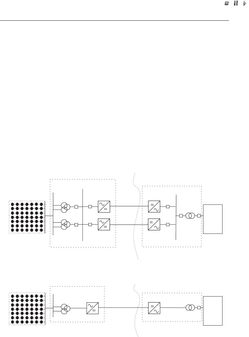
A VSC based HVDC transmission system consists of the following main components:
an AC based collector system within the wind farm; an offshore substation with the
relevant converter(s); DC cable pair(s); an d an onshore converter station [Ha
¨
usler and
Owman, 2002; Eriksson et al., 2002; see also Figure 22.5].
A VSC based HVDC link does not require a strong offshore or onshore AC network;
it can even start up against a nonload network. This is possible because in a VSC the
current can be switched off, which means that there is no need for an active co mmuta-
tion voltage. Furthermore, the active and reactive power supply can be controlled
independently. In addition, it is important to mention that the VSC based HVDC
488 Transmission Systems for Offshore Wind Farms
//INTEGRAS/KCG/P AGIN ATION/ WILEY /WPS /FINALS_1 4-12- 04/0470855088_ 23_CHA22 .3D – 489 – [479–504/26]
17.12.2004 10:46PM
connection is usually not connected to ground. Therefore, the VSC based HVDC always
needs two conductors (cables).
VSCs use IGBT semi conductor elements with a switching frequency of approximately
2 kHz. This design results in comparatively high converter losses of up to 2 % per
converter station. Rese arch currently focuses on how to reduce these losses. The
advantage of the high switching frequency are low harmonic levels and, hence a reduced
need for filters. Also, the rating per converter is presently limited 300–350 MW, while
the cable rating at 150 kV is 600 MW. Hence, if more power than 300 MW is to be
transferred, the number of converter stations has to be increased [see Figure 22.5(a)]. It
is, however, e xpected that the avail able converter rating will be increased to approxi-
mately 500 MW by the market leader in the near future. Figure 22.5(b) shows the
possible design for a 500 MW offshore wind farm based on converter stations with a
500 MW rating.
The total efficiency of the two converter stations of a VSC based HVDC system is less
than that of a LCC HVDC system. There is hardly any information on the total system
efficiency published, but at the International Workshops on Transmission Networks for
400 kV
Offshore substation
(a)
Offshore wind farm
Shore line
Onshore
network
150 kV
30 kV
600 MVA
150 kV
300 MVA
300 MVA
300 MVA
300 MVA
300 MVA
300 MVA
Onshore converter
station
Bipolar cable pair
Rating: 600 MW
+/–150 kV
Bipolar cable pair
Rating: 600 MW
+/–150 kV
400 kV
Offshore substation
Offshore wind farm
(b)
Shore line
Onshore
network
500 MVA
500 MVA
30 kV
500 MVA
150 kV
500 MVA
Onshore converter station
Bipolar cable pair
Rating: 600 MW
+/–150 kV
150 kV
Figure 22.5 (a) A 600 MW wind farm using two voltage source converter (VSC); high-voltage
direct-current (HVDC) systems, each converter station with a 300 MW rating. (b) A 500 MW wind
farm using one VSC HVDC system based on a converter station with a 500 MW rating
Source: for part (a) based on Eriksson et al., 2003.
Wind Power in Power Systems 489

//INTEGRAS/KCG/P AGIN ATION/ WILEY /WPS /FINALS_1 4-12- 04/0470855088_ 23_CHA22 .3D – 490 – [479–504/26]
17.12.2004 10:46PM
Offshore Wind Farms of 2000 to 2003 the total efficiency, including both converter
stations, was reported to lie in the range of 90–95 %.
Other often-emphasised advantages of a VSC based HVDC solution is the capability
of four-quadrant ope ration, the reduced number of filters required, black-start cap-
ability and the possibility of controlling a number of variables such as reactive power ,
apparent power, harmonics and flicker when feeding the power system from a VSC
(Burges et al., 2001; Ko
¨
nig, Luther and Winter, 2003).
22.3.4 Comparison
The following comparison of the three different technical transmission solutions is
divided into technical, economic and environmental issues.
22.3.4.1 Technical issues
The relevant technical issues are: rating, losses, size of offshore installation, grid impact
and implementation issues.
Rating
Presently, AC cables have a maximum rating of about 200 MW per three-p hase cable.
This rating is based on a voltage level of 150–170 kV, compensation at both ends of the
cable and a maximum cable length of around 200 km. For shorter distances, voltage
ratings may increase to 245 kV, which would raise the maximum rating to 350 MW over
a maximum of 100 km, or 300 MW over 150–200 km (Rudolfsen, 2001). Bipolar cable
pairs for VSC based HVDC, in comparison, can have a maximum rating of 600 MW for
a voltage level of 150 kV, independent of the cable length. Currently, only converter
stations with a maximum rating of 300–350 MW are in operation, which means that two
converter stations would be needed for the full utilisation of the maximum cable rating.
Converter stations with a maximum rating of 500 MW, however, are announced to be
becoming available in the near future, which will reduce the number of cables required
for VSC based HVDC solutions (see Table 22.2).
Table 22.2 Number of cables needed for different wind farms and different technical solutions
Wind farm
capacity (MW),
100 km transmission
distance
HVAC
(150 kV)
LCC HVDC VSC HVDC (150 kV)
150 kV,
bipolar
cable
450 kV,
monopolar
cable
300 MW
CS rating,
bipolar cable
500 MW
CS rating,
bipolar cable
300 2 1 þ 11 1þ 11þ 1
500 3 2 þ 21 2þ 21þ 1
900 5 4 þ 42 3þ 32þ 2
1200 6 5 þ 52 4þ 43þ 3
Note:CS¼ converter station; HVAC ¼ high-voltage alternating-current; HVDC ¼ high-voltage
direct-current; LCC ¼ line-commutated converter; VSC ¼ voltage source converter.
490 Transmission Systems for Offshore Wind Farms